
I started out today by trimming the inside edges of each elevator to get the gap between the inboard elevator edge and the fuselage sidewall to about 0.1″. I had a discussion with my build buddy Marco earlier about these… specifically the fact that with the Cozy-style torque tube offsets, it really creates a bigger gap at the forward edge of the elevator where the elevator control tube bolts to the torque tube assembly flange. Marco suggested an inboard fairing, which I had already been mulling over. At one point I really liked how they looked, but after seeing the simplicity of the elevators against the sidewall, for some reason that really appeals to me. Moreover, “simplicity” is the key word here in that I don’t want to add another 4-8 hours on the build messing with inboard fairings. (Later in the evening I was emailing back & forth with my buddy Dave down in Australia …. he likes the fairings too! It’s a conspiracy against me, I tell ya! ha!)
Ok, so in the grand scheme of things my thought is that a 0.1 to 0.125″ gap is not going to bust the curb appeal of this bird. In fact, by the time the inboard ply of BID and a little micro goes on the fuselage side for finishing, I suspect it will be very close to 0.1″ max of a gap. So . . .
Set & match.
Done! And moving on!
(Sorry Marco & Dave … guess you guys will just have much more awesomer airplanes than me!)
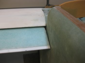
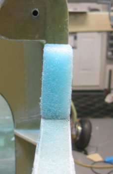
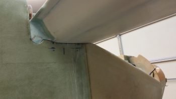
Here’s the gap on the left side again. Note how it is wider as it gets closer to that torque tube offset flange near the control tube.
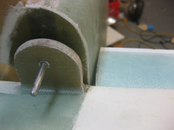
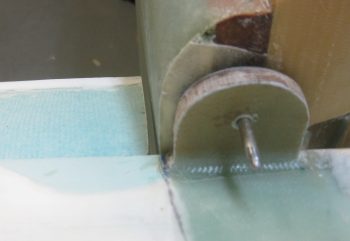
And the right side. Not as distinct of a gap near the torque tube offset flange.
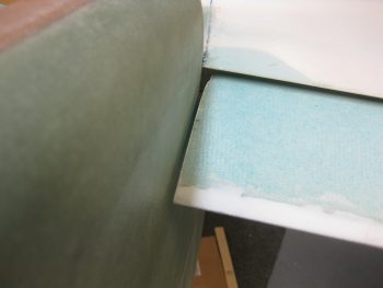
Another view of the right side elevator gap.
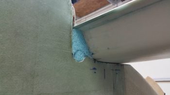
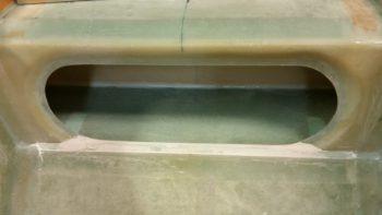
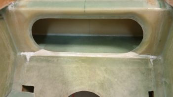
Ok, first issue solved! (For now!). I then moved on with figuring out how to seal the gaping hole on aft side of the canard when mounted into the fuselage. Here I have Cozy-style torque tube offsets that operate concentrical & thus only require a round hole with a very small gap around the traversing tube (versus the SLOT that the stock elevator torque tubes require on the side of the fuselage), and yet immediately in front of it is still a huge open gap that must be filled in lest the cold air continue to spilleth into my craft.
I called Chrissy from the Cozy Girls since A) they make these parts, and B) they installed these parts on their Cozy. She confirmed my idea that you simply create a small piece of “fuselage wall” on the aft side of the canard so that when the canard is removed in somewhat normal fashion, then the “false” wall piece comes off with the canard. I asked this question of Dave B. down in OZ and he confirmed it with a simple diagram that is actually in the Cozy plans, that shows this small filler piece.
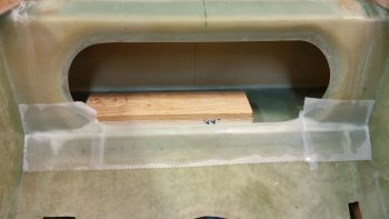
With a scant bit of knowledge in my brain, I trudged forward in order to defeat the evil dark forces that is COLD AIR spilling into the cockpit! I collected a bunch of 3/4″ pieces of Divinycell foam but then quickly realized that while these side walls do contain 3/4″ pieces of Divinycell foam, they are certainly not 3/4″ thick after a fair amount of glass laid up upon them (more like 0.87″). So, to get the right current thickness of the fuselage side wall and then also to save weight –since this is only really a plug to block air– I decided to use blue wing foam and cut/shape the starting block foam myself.
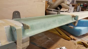
I started with the right side…
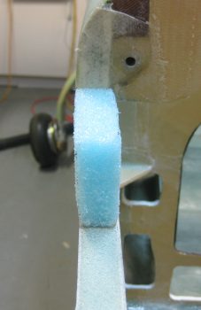
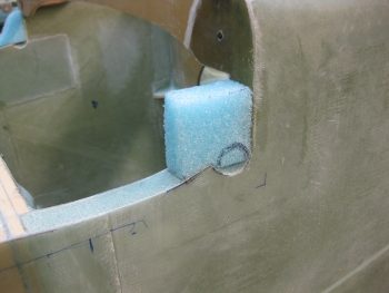
And first shaped the bottom angled portion and the aft vertical edge (aft is left in pic).
I then eyeballed it with some test fitting on the canard TE to take a good majority of the foam off the front side of it, where it mates to the canard TE.
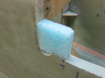
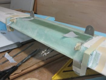
Here’s the left side piece…
Initial fitting…
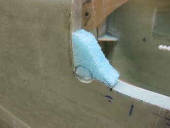
And more foam removed from the front side (of the left piece) in prep for final shaping.
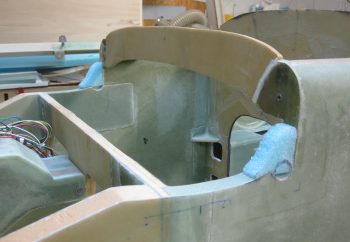
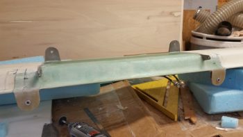
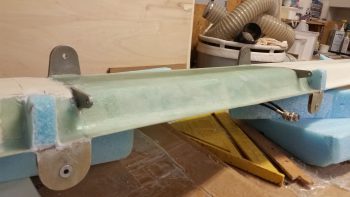
I then finalized the shaping & fit of the canard aft filler pieces on the canard itself. With these about 70-80% good on shape, I then remounted the canard . . .
And finalized the shaping & fitting of the canard filler pieces. I’ll remove the circular area for the torque tube offset cross tube after I glass the filler pieces in place.
I then removed the canard and lightly Dremelled & sanded the finish off about 1″ outboard of each filler piece in prep for a 1-ply BID layup on each side of the respective filler pieces.
I then taped up the areas around the filler piece mounting locations for a little anti-gunk protection.
I then whipped up some micro and glued the pieces in place.
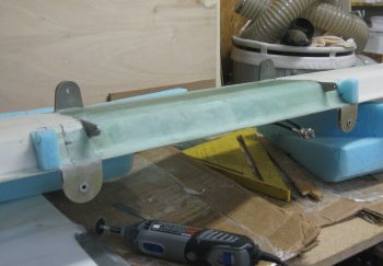
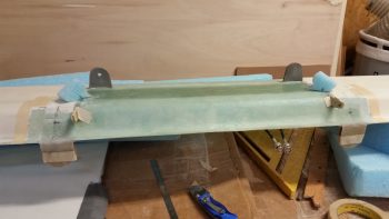
I taped the canard filler pieces in place and let them cure for a bit to allow them to better hold their position on the TE when I laid up a BID ply on each side.
As the micro was setting up I mixed up some pour foam and filled in the holes at the inboard end of each elevator (these are holes that I had to make to bolt the elevator tube to the outside torque tube offset connecting piece). I also filled in the gap at the top of the GIB seat & the CS spar (pour foam pics shown below).
A bit later I whipped up some more epoxy & flox. I created flox fillets in the corners of each filler piece & canard junction (pic below). I then laid up 1 ply of BID on each side of each filler piece overlapping from a 1/2″ to 1″ onto the canard TE (sorry, I didn’t get a pic of the actual layup).
Since the garage was about 68°, I set up heat lamps on the filler piece layups and let it cure for a while as I sanded the GIB seat back top in prep for glass (again, pics below).
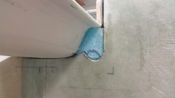
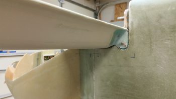
Here’s how my canard filler pieces came out. They need a bit more tweaking on the fit & finish, but definitely not bad at all. I’m really happy with how they turned out!
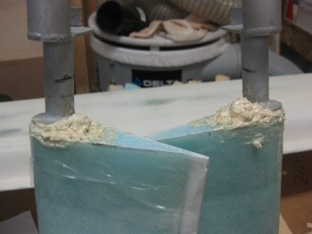
Here’s a shot of the pour foam in the inboard ends of the elevators. Note the torque tube offset flanges that I discussed earlier… you can see them peaking out of the piles of foam.
Here’s the pour foam application on the back seat / spar junction where there was still a slight gap after I embedded a foam wedge/spacer in between the seat back & spar.
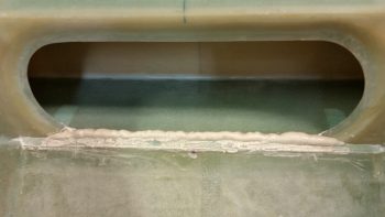
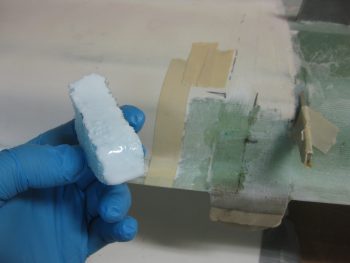
And a closeup shot of the pour foam…
I then sanded the entire foamed area and the glass areas that would receive BID tapes.
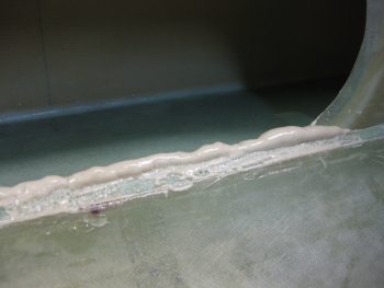
I then mixed up some epoxy, micro & flox. I micro’d the fresh foam surfaces and then floxed some slightly uneven glass transitions (mainly from previous BID tape layups) towards the corners.
I then laid up three separate 2-ply BID tape segments: 2″ wide x 4″ long in each corner, and 2.25″ wide x 11.5″ long for the center piece. Admittedly, the overlap of the center BID tape was only about 1/4″ over each of the outboard corner BID tapes, but I think that will be fine for this application.
By the time I finished peel plying this layup, the MGS epoxy with fast hardener I was using was getting very tacky. Since the temps outside were dropping to the mid-40’s F, I went ahead and put a couple of heat lamps on the layup. I then cleaned up, brought the wings a motorcycle back into the shop and then uploaded these pics to the site. I then checked the layup well over an hour later and all looked good, so I took one of the heat lamps away & simply left the other one on to keep the layup above ~70° F overnight.
Tomorrow I’ll continue to work on the canard filler pieces, and try to get the micro inset around the torque tube offset cross tube that traverses the fuselage sidewall.