
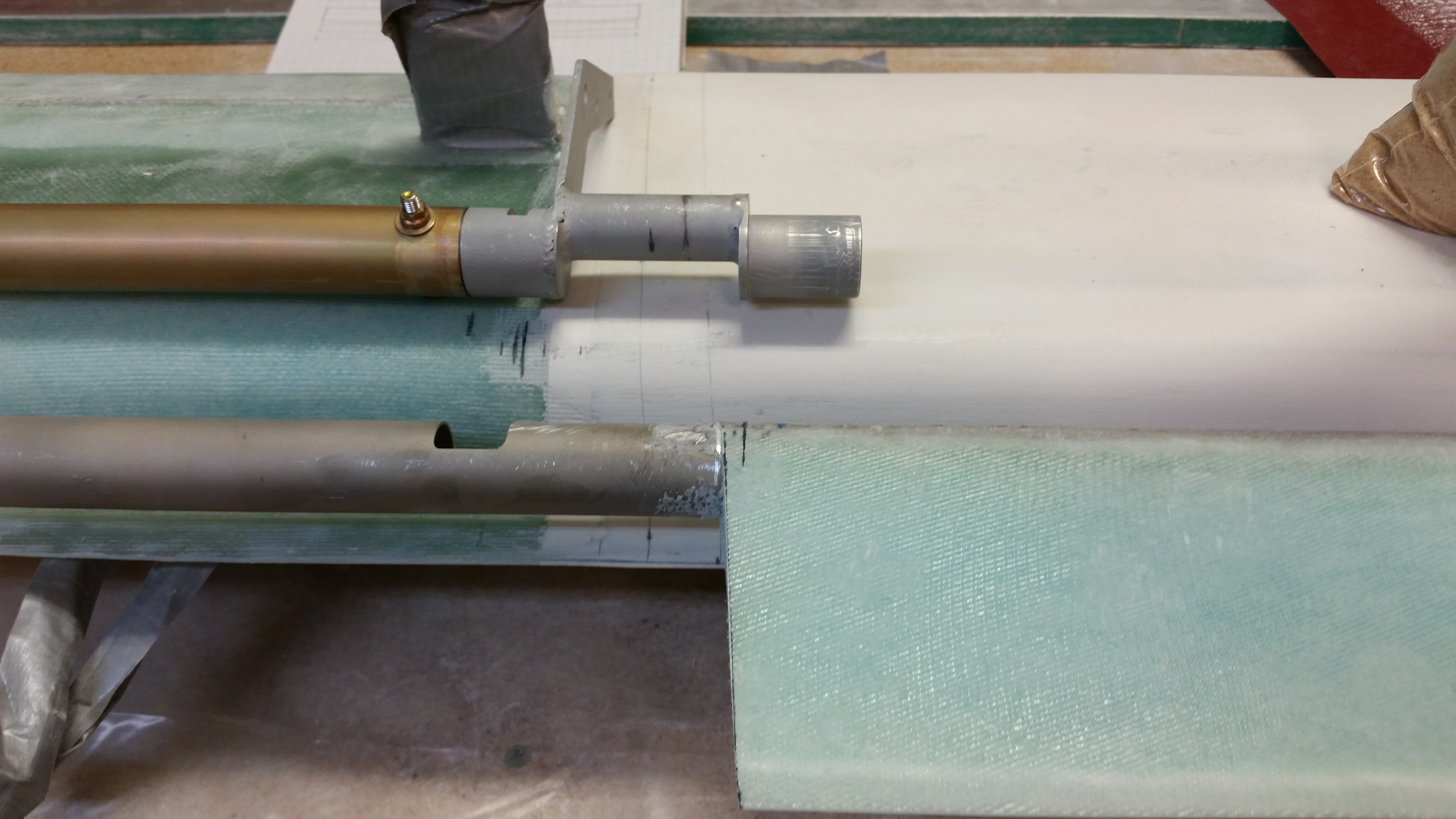
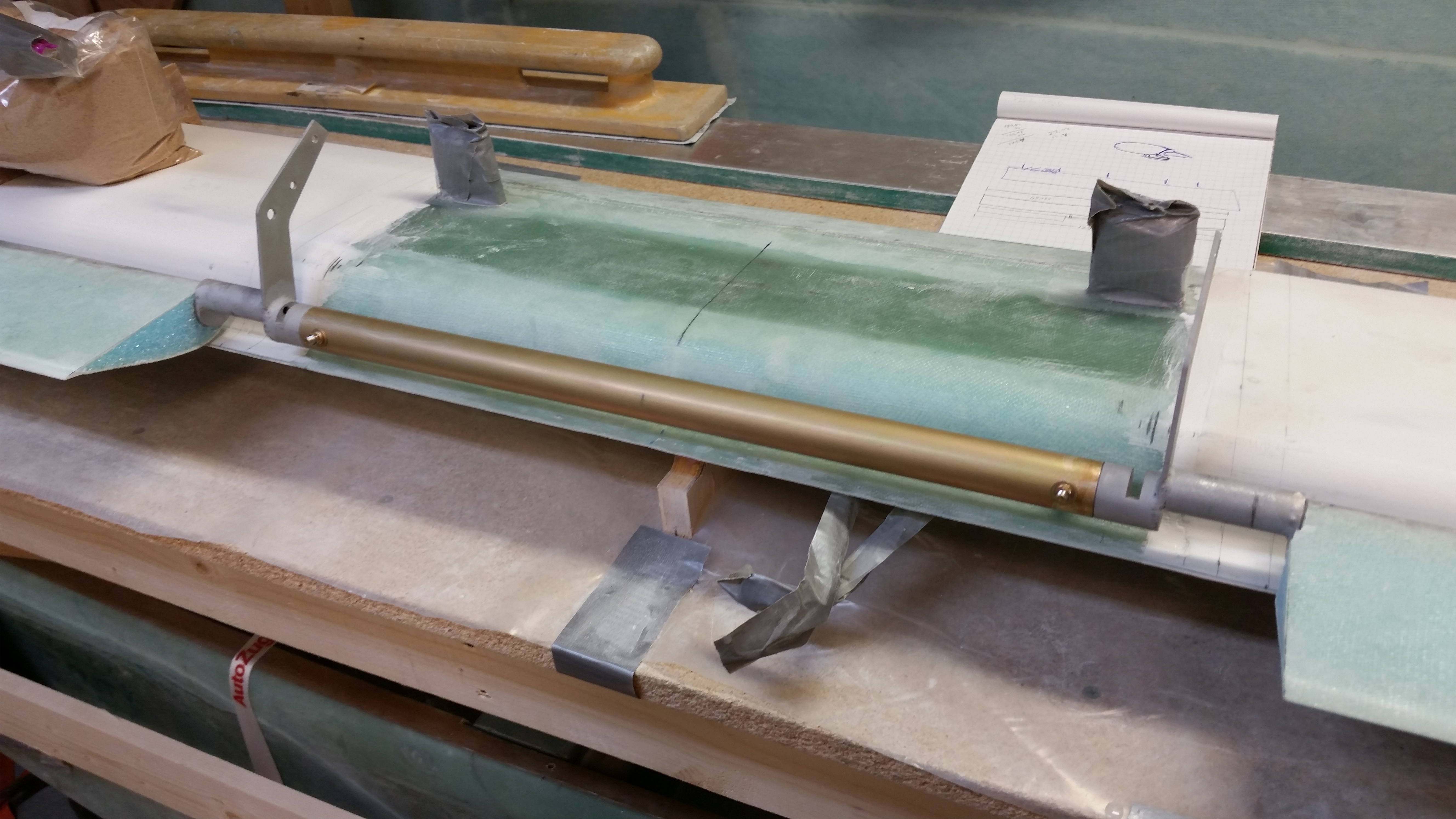
I started off today by nailing down the required length of the elevators in order to get the spool tube & offset assembly mounted to the elevators. In the picture below, the torque offset at each end of the center spool tube assembly needs to be inserted into the inboard elevator tube, drilled and secured with an AN3 bolt on the respective elevators.
To get the two elevators and center spool tube assemble bolted together, I first needed to know what the required length for these individual pieces are when they’re attached as one. Obviously if it’s all too long then it won’t fit inside the swoosh tip end caps (and the hinge & hinge hard points won’t align), and clearly being too short in length causes problems as well.
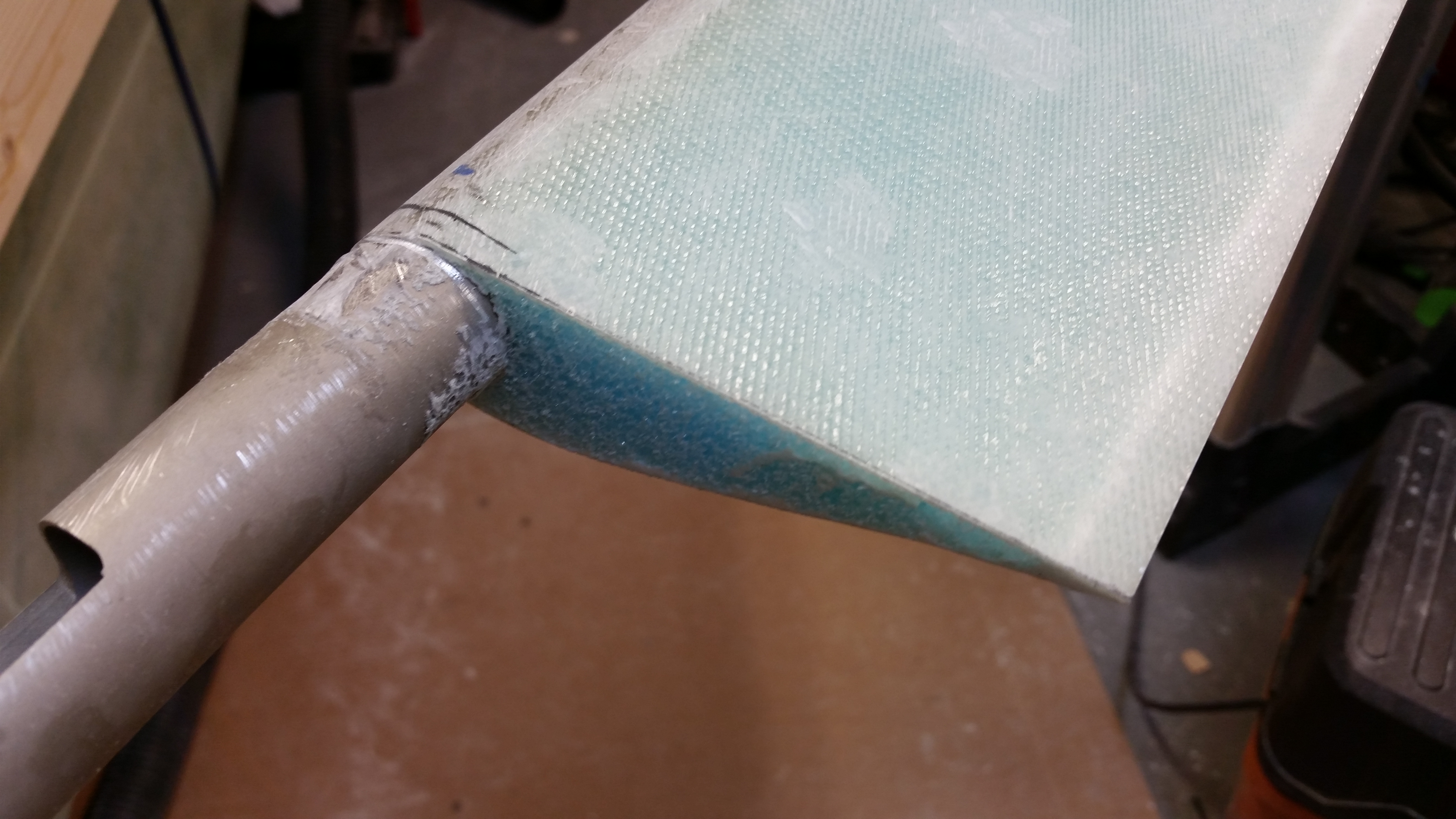
I needed to keep account of the 1/16″ minimum clearance between the outboard elevator edge and the not yet glassed swoosh tips. The Cozy elevator plans say 0.1″ and I’ve also heard a 1/8″ gap bantered around as well. I started with 1/16″ inch, but then using a popsicle stick ended up with about a .083″ gap (or around 5/64″ of an inch). With the outboard elevator edges good, I moved inboard to figure out where I needed to cut the actual elevator, and its shape, and then where I would need to cut the actual elevator tube on each side to ensure all these dimensions would synch up.
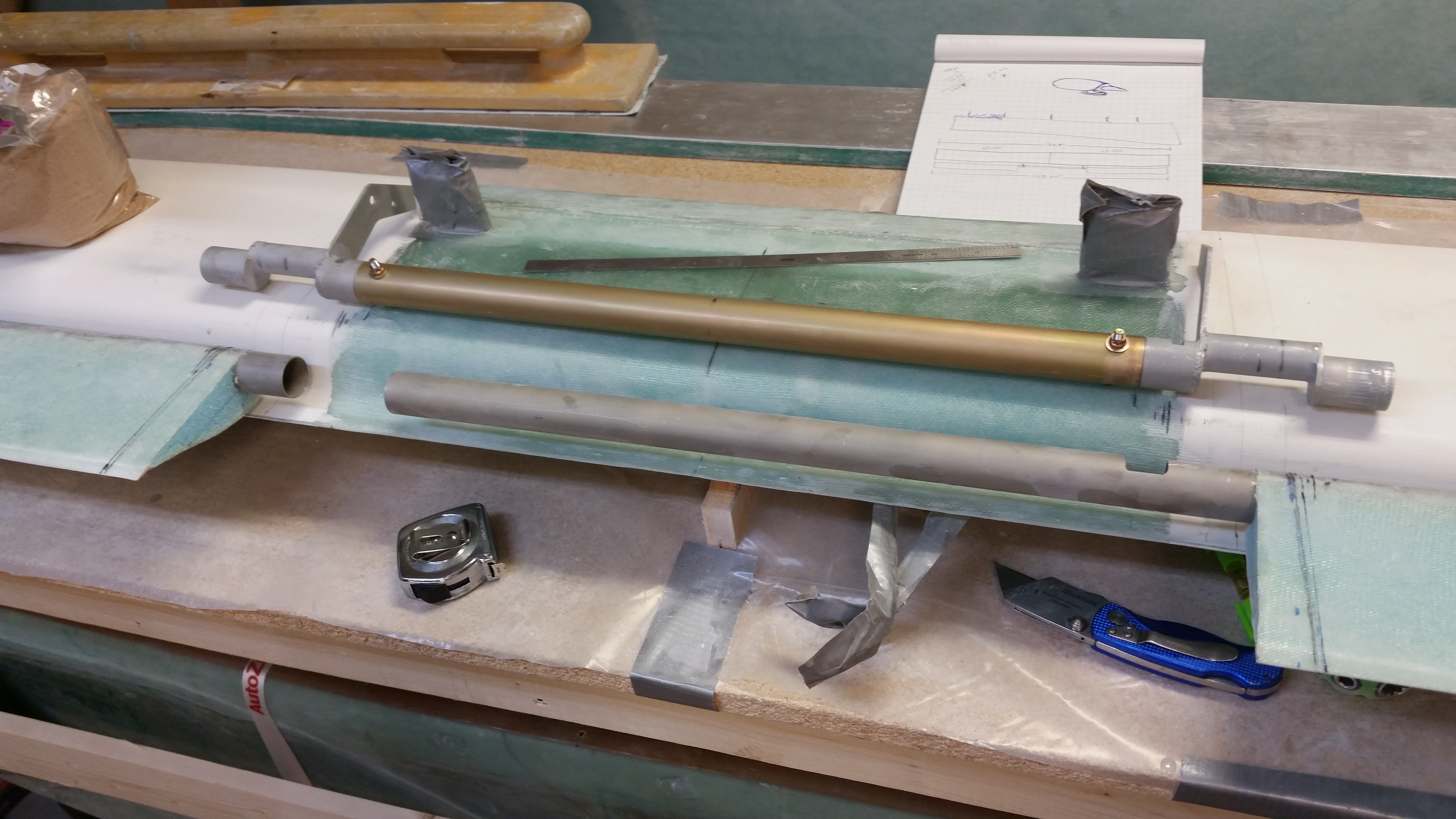
I’d like to point out, for those that may still be slightly confused as to what I’m doing here with this whole “Spool Tube Assembly” thing that the Long-EZ clearly doesn’t have per plans. The pic above is perfect for showing the “old” Long-EZ way of installing the elevators, with the longer left elevator tube crossing the fuselage and then both torque offsets getting mounted together within an inch or so of each other on the right side of the fuselage. Sitting atop the canard in the above pic is the “new” way, or simply installing torque offsets from the Cozy. Since the Cozy has a control stick on the fuselage (cockpit) sidewall both left and right, then it stands to reason there’s a torque offset on each side of the fuselage to connect to the control stick linkage. The “spool tube” merely connects the two torque offsets, and thus the elevators, from one side to the other. Again, to explain WHY I’m dong this, I’ll quote the part description from the CG Products web site (In short, it turns the banana-shaped hole into a small round hole so you don’t freeze your tootsies off in flight!):
While not a “per plans” part in the Long-EZ, these parts solve the serious draft problem in the Long-EZ where the eccentric moving elevator torque tubes come through the fuselage walls. This is accomplished by shifting a portion of the mechanism to be concentric with the hinge axis.
Once I got the outboard elevator ends figured out, I installed the hinges and marked the locations of the hinge slots on the canard on both sides.
I then removed the elevator, removed the hinges so as not to cut the 3/16″ stainless steel hinge pin by accident. I transposed the marking on the bottom of the elevator to the top, and checked the accuracy of my marks by drilling a 1/16″ hole straight through the elevator from the bottom to the top . . . right on the line each side!
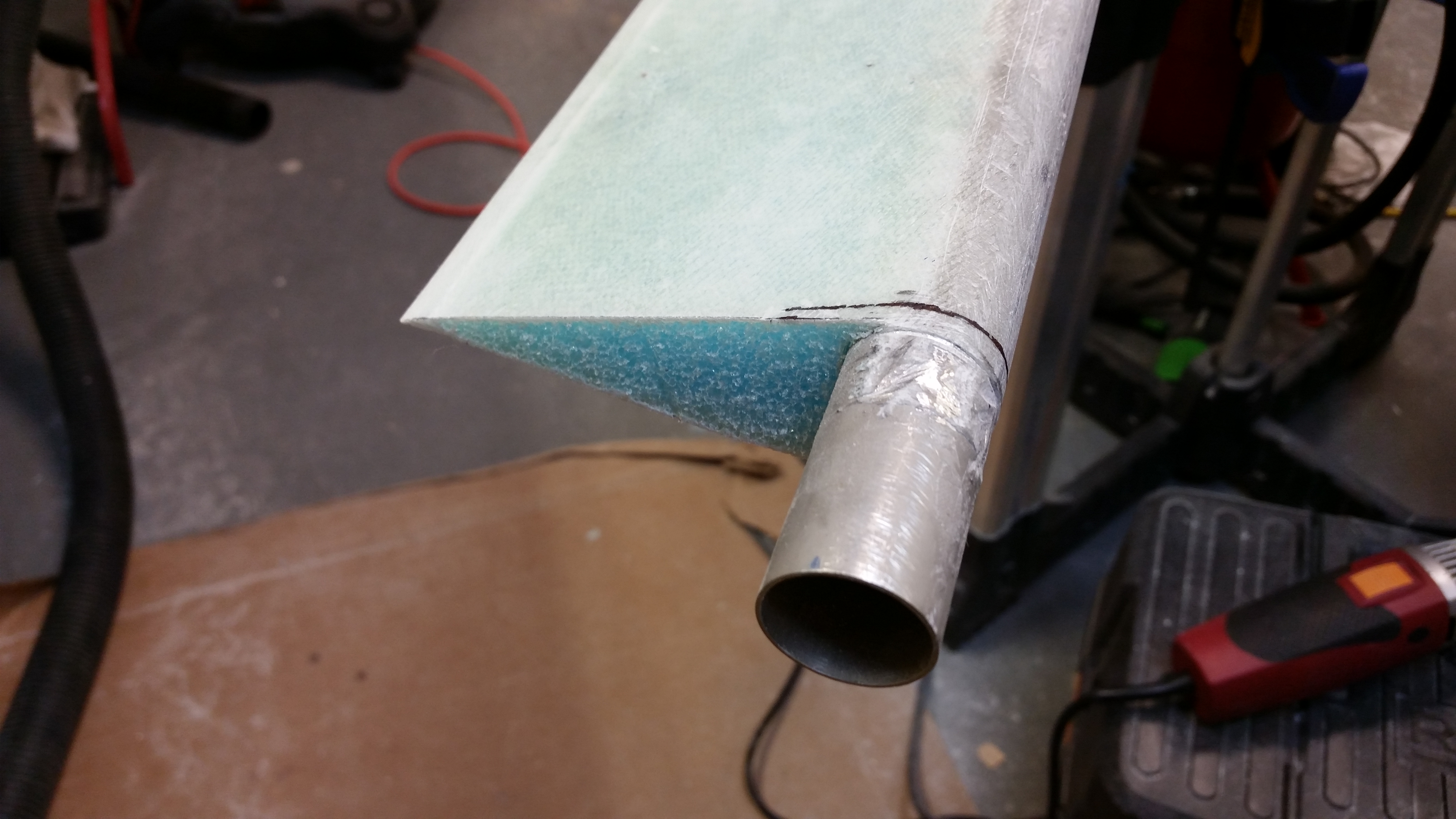
I then used the Fein saw to cut through the elevator skin & foam.
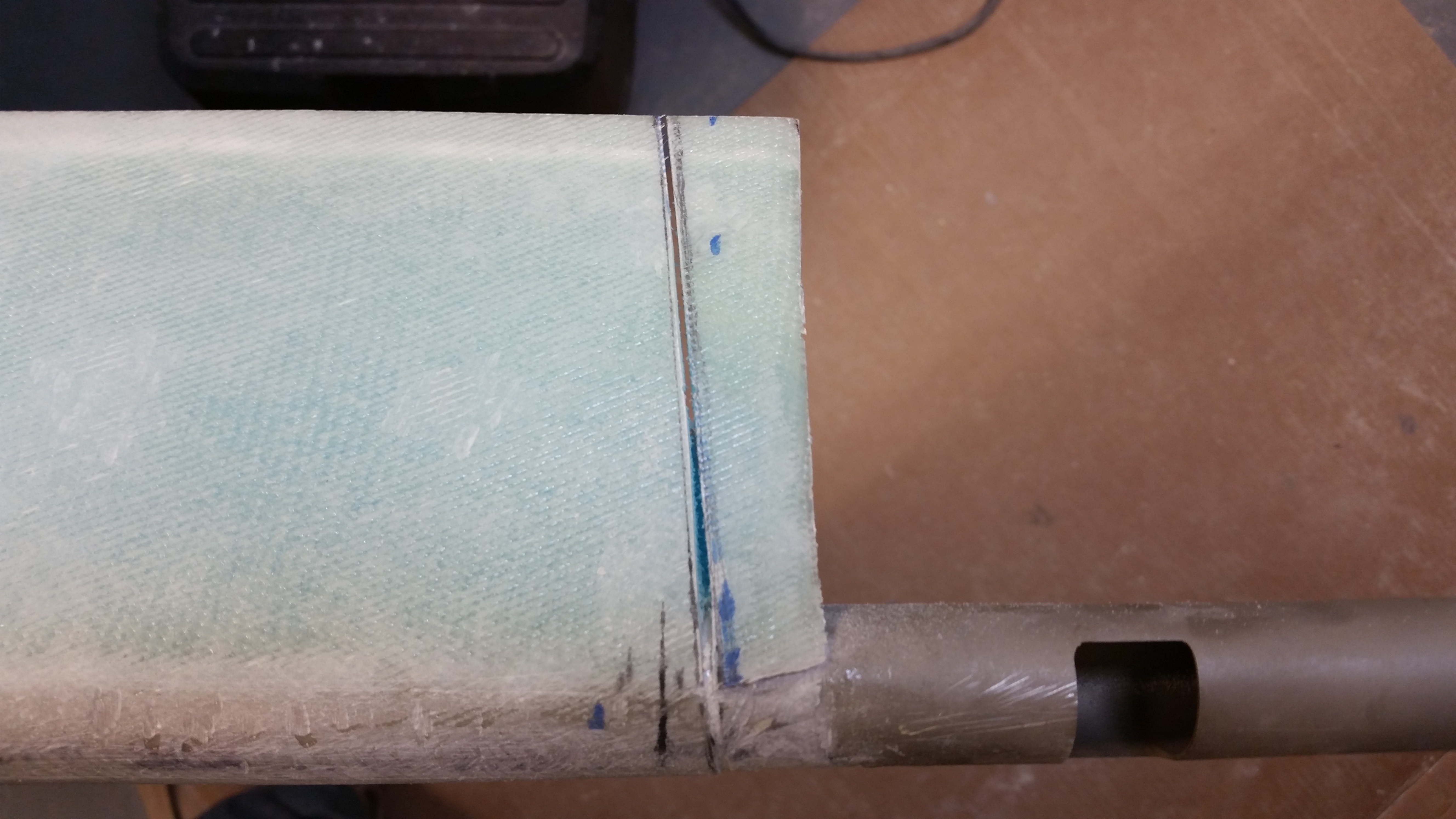
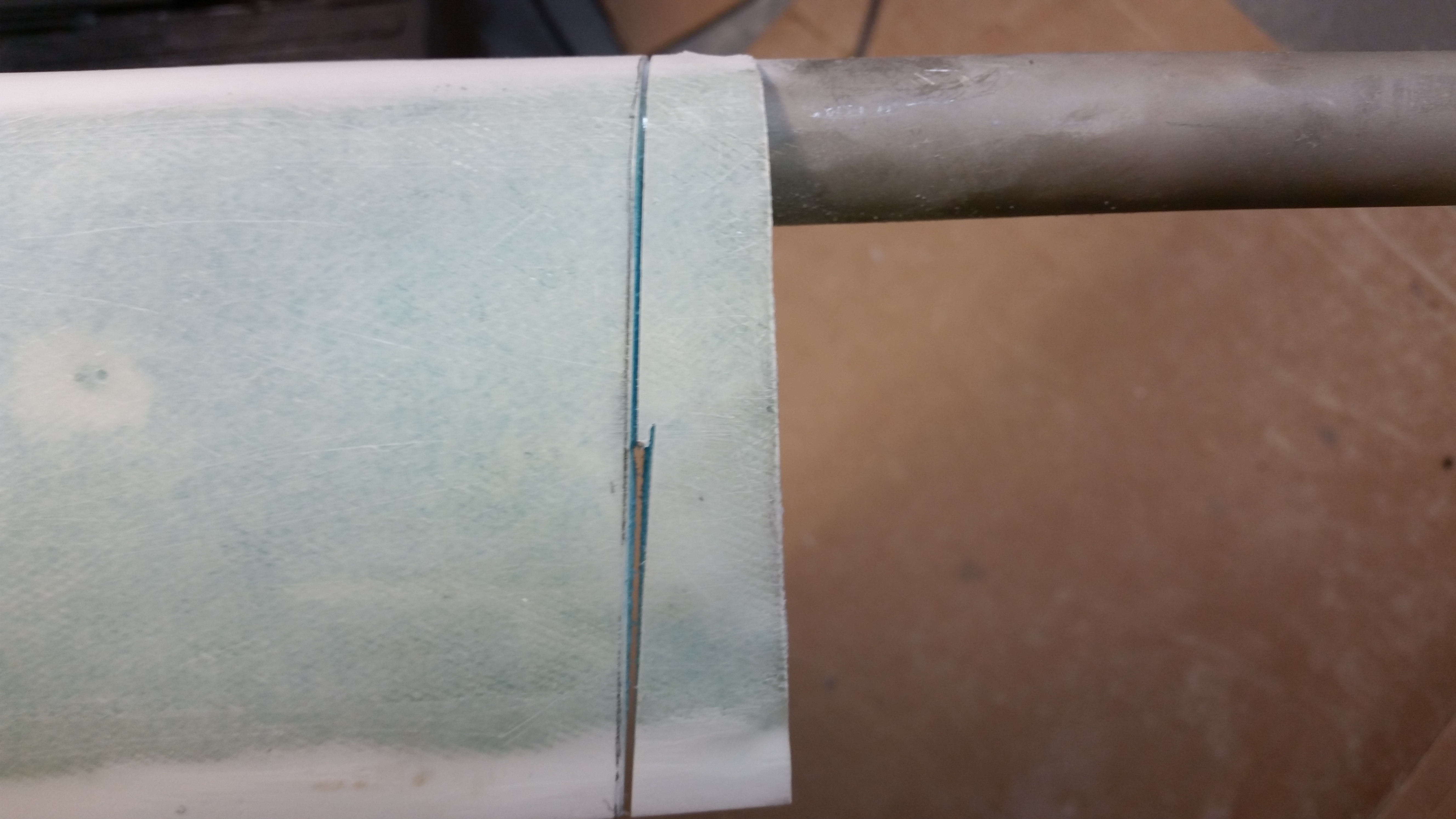

Here’s the final product:
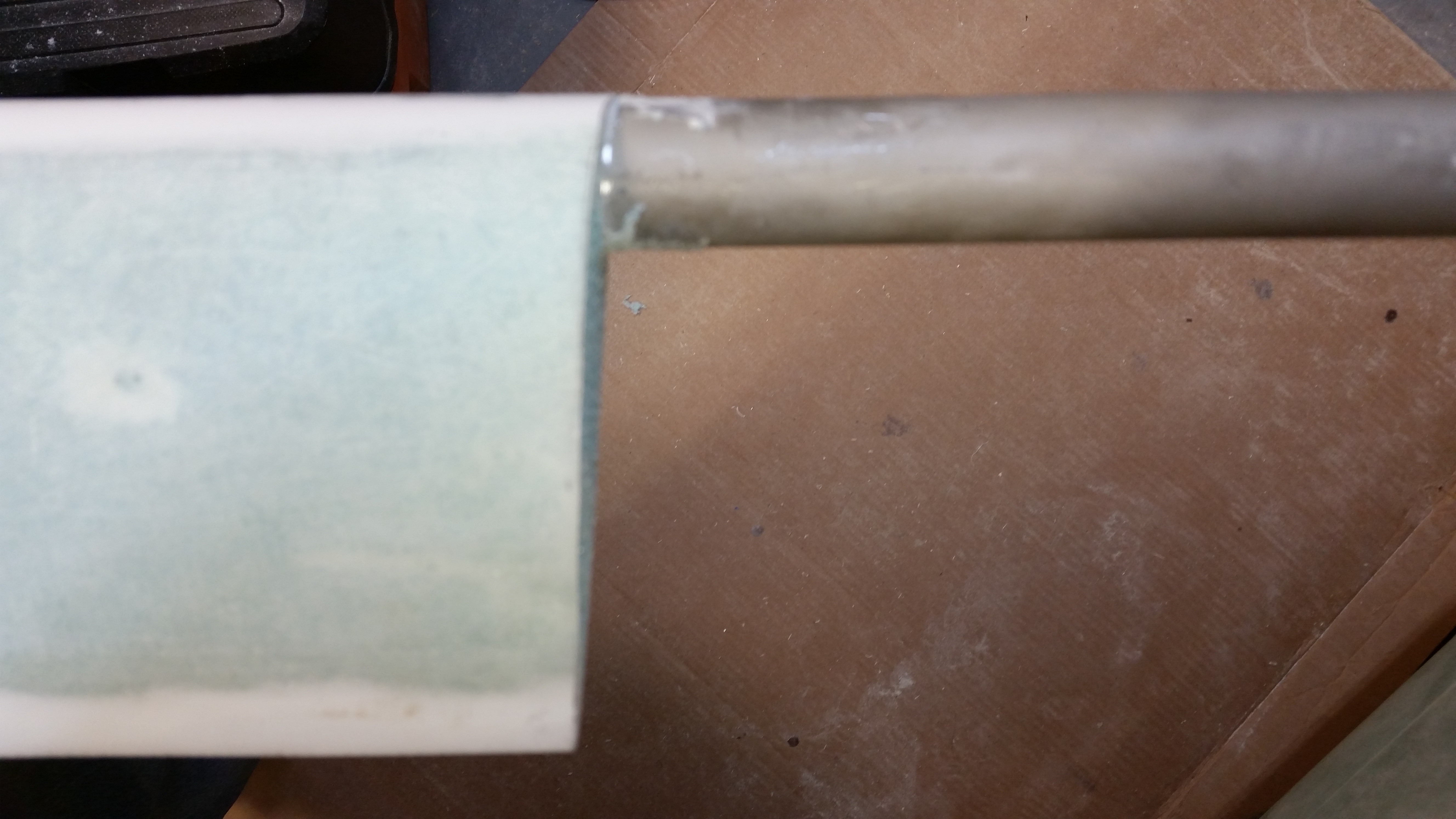
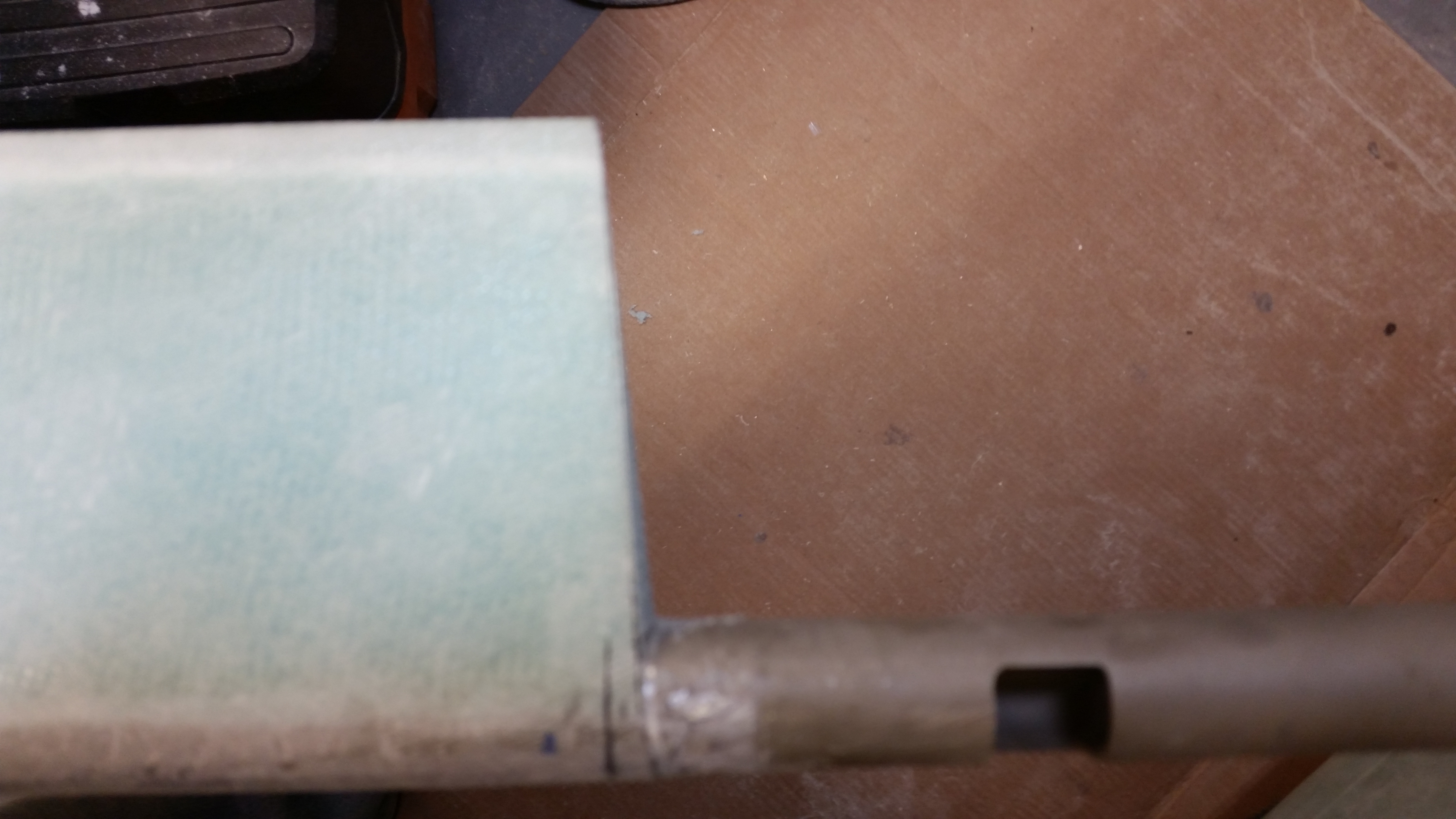
After trimming the inboard elevator on the other side, I marked up the actual aluminum tube to be trimmed down.
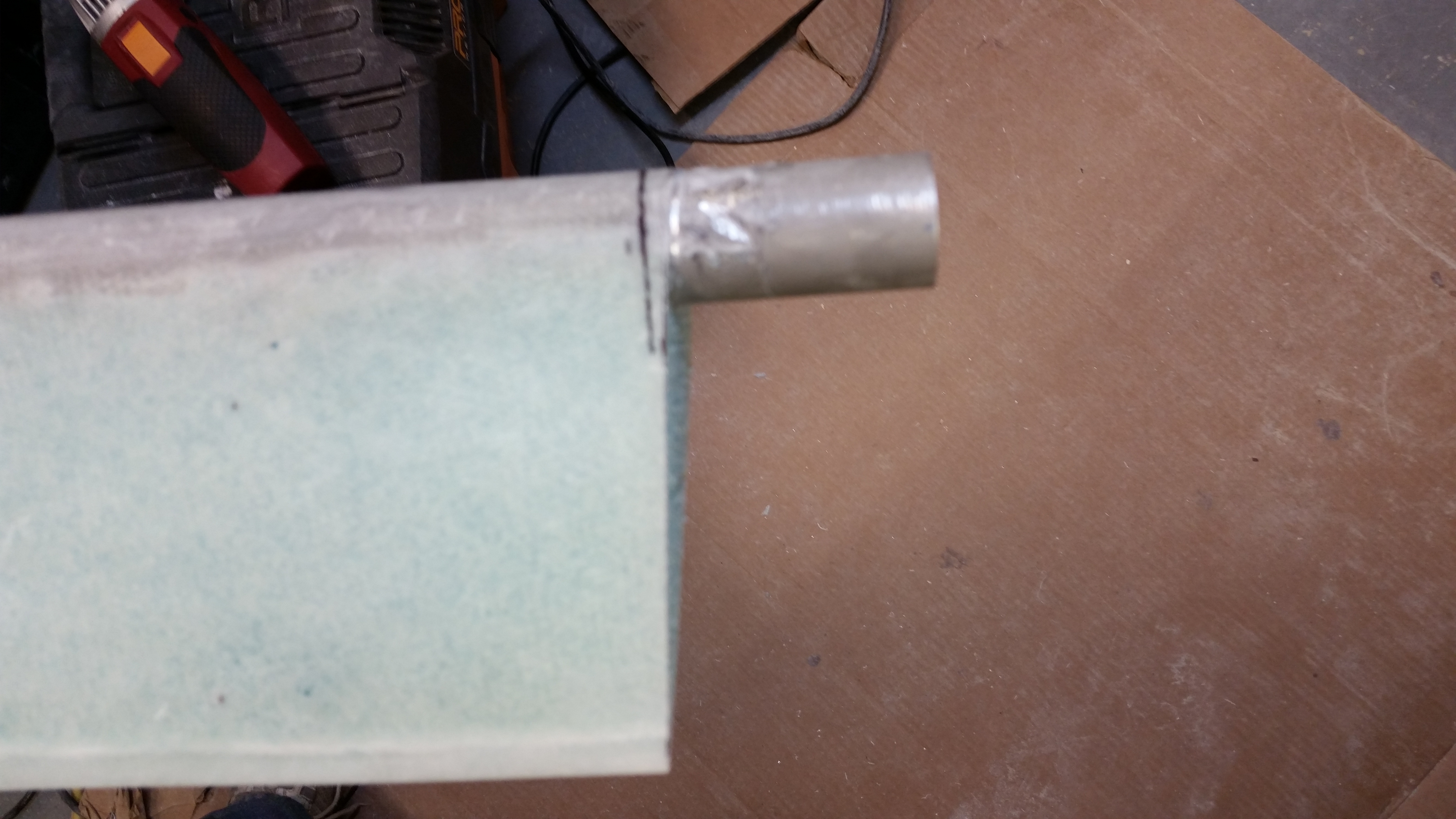
I ended up cutting one elevator tube with the chop saw, and the other side–in trying to conserve more of the elevator’s inboard edge shape–with the Dremel tool, then sanded it to length.
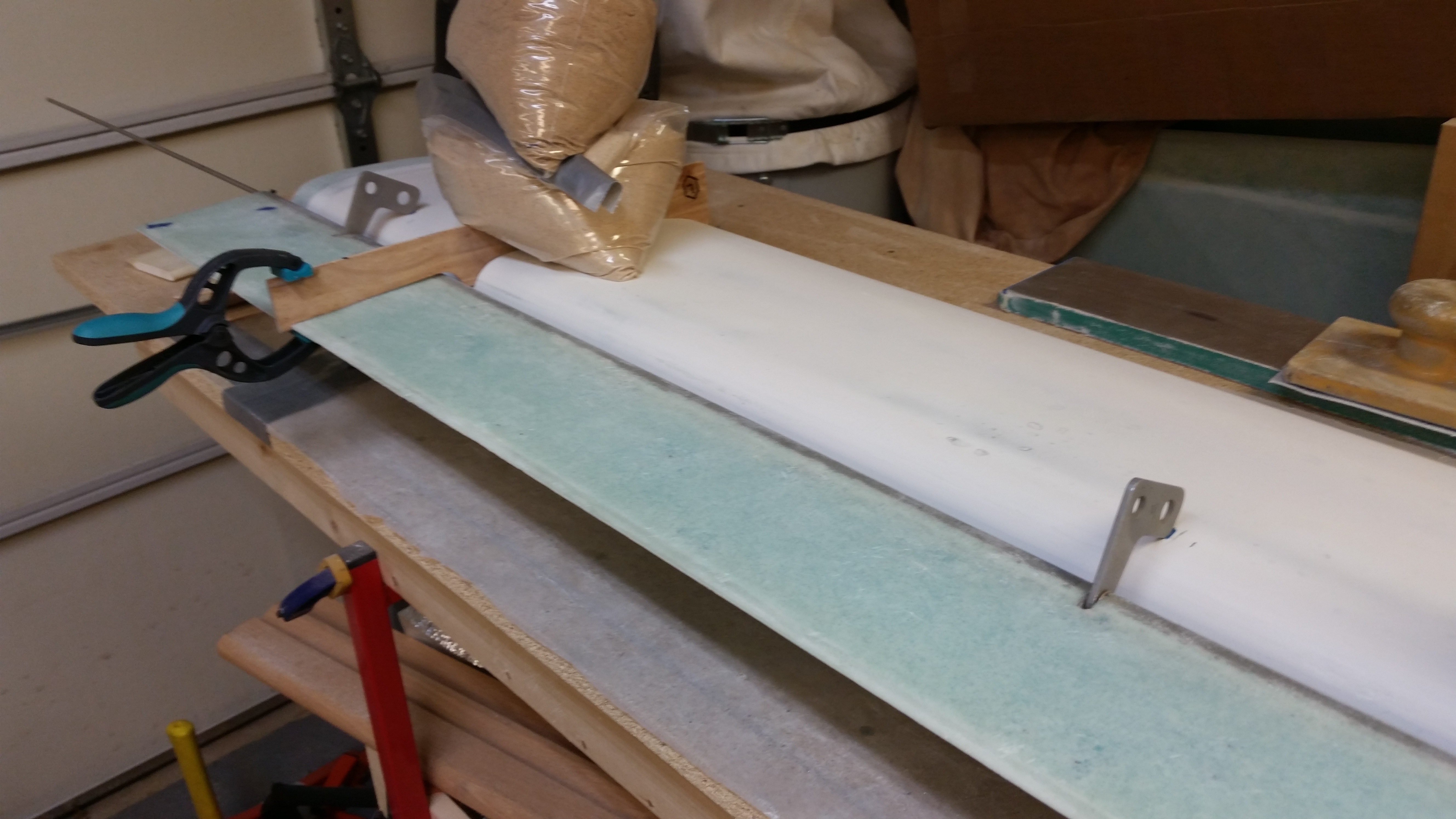
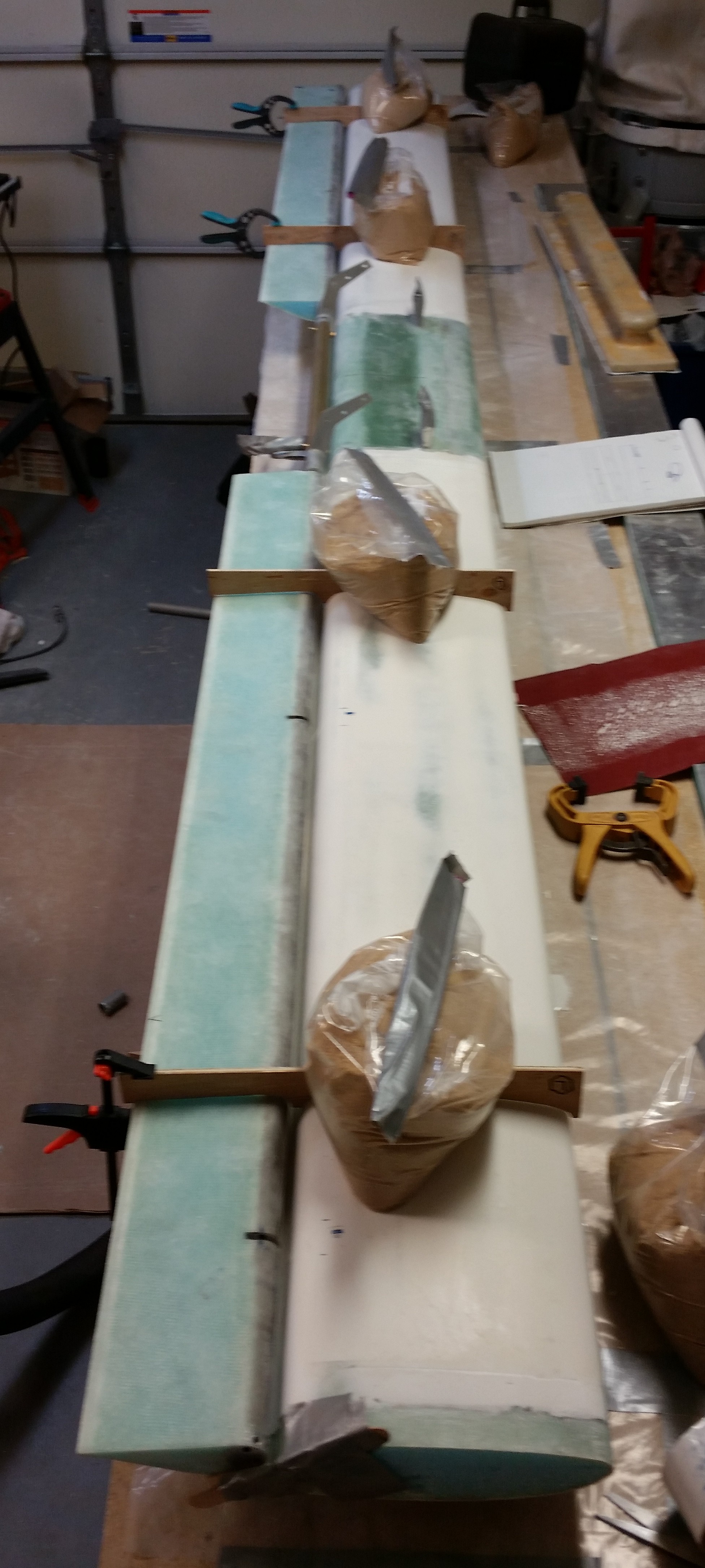
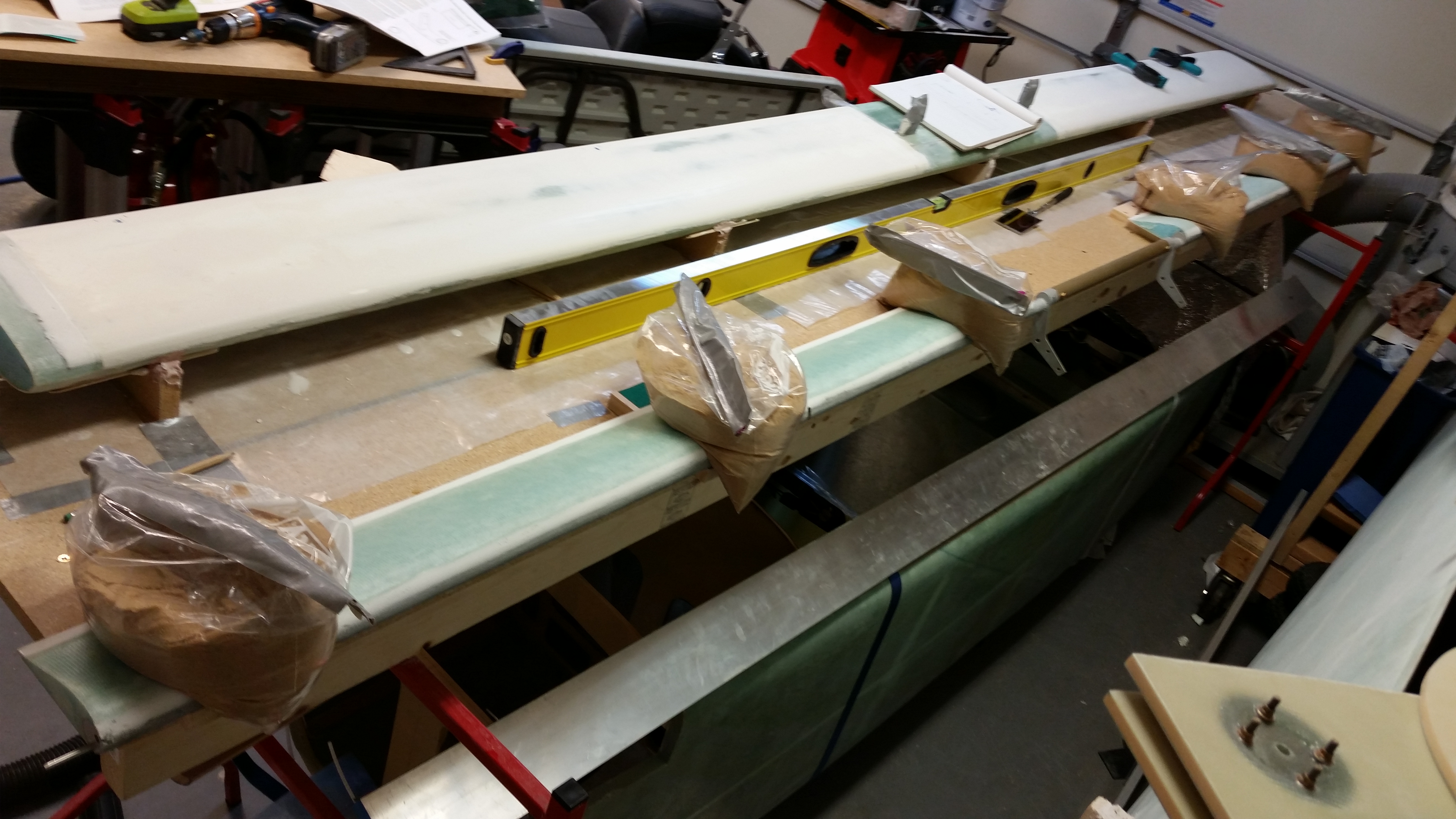
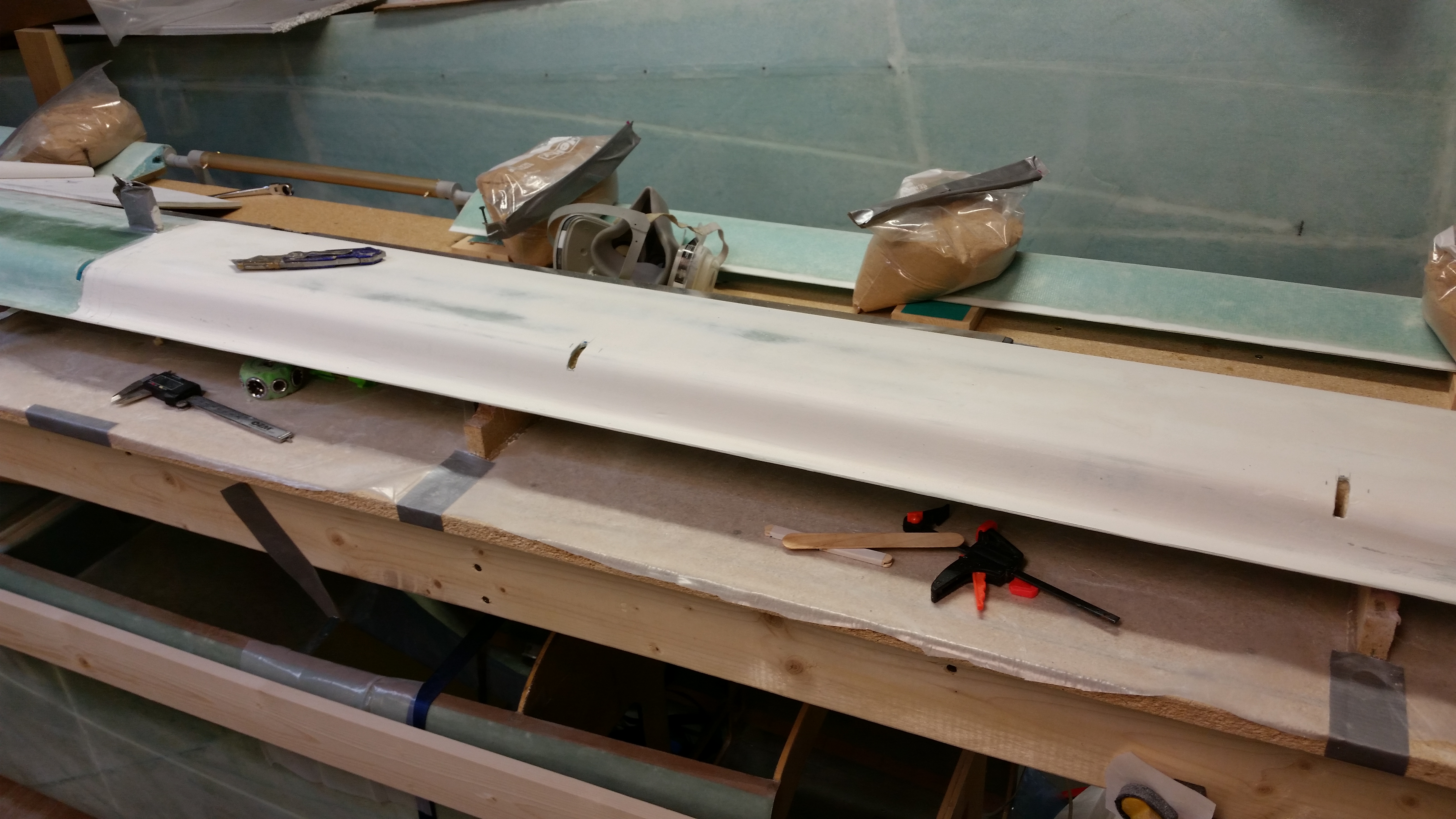
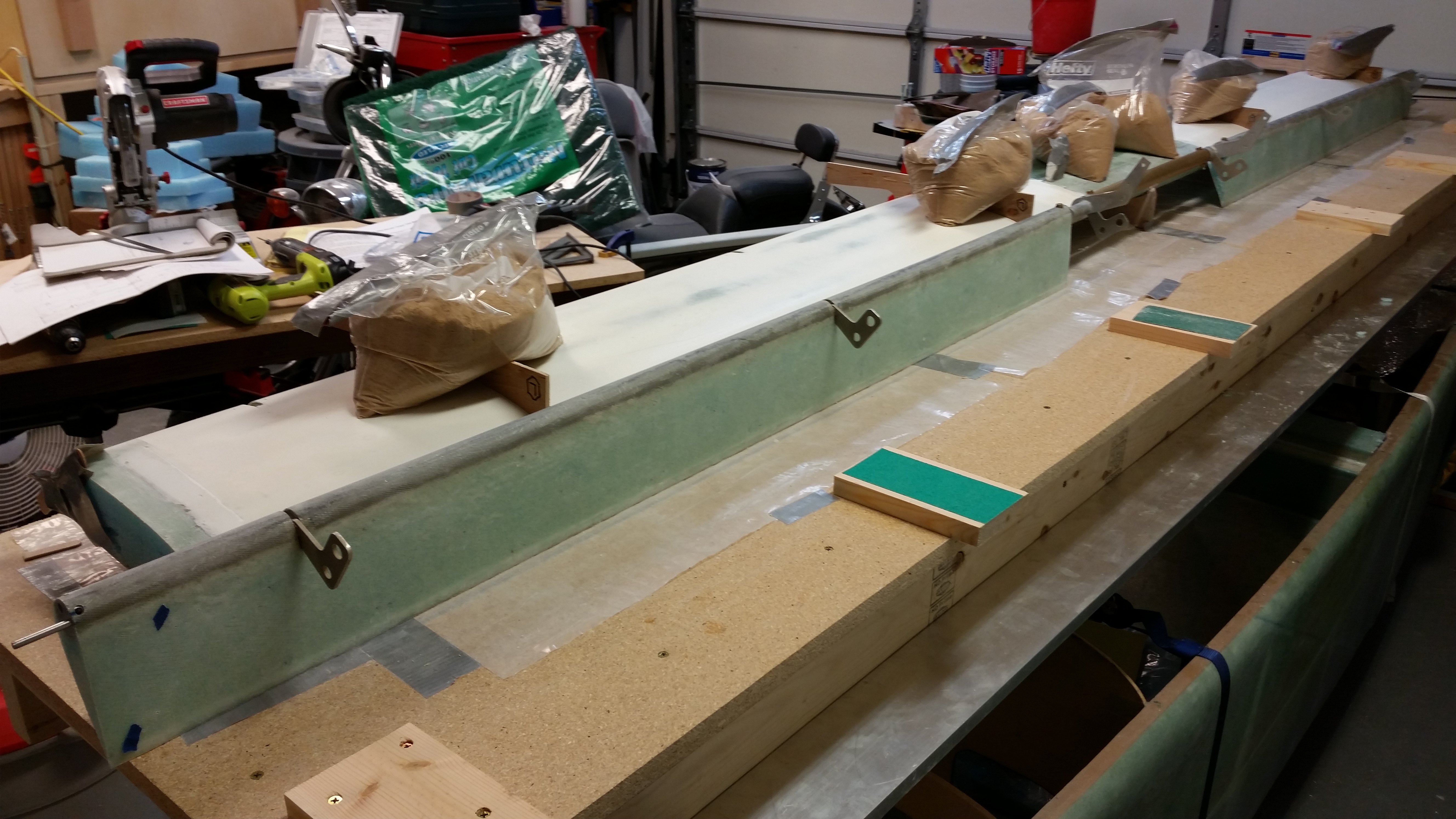
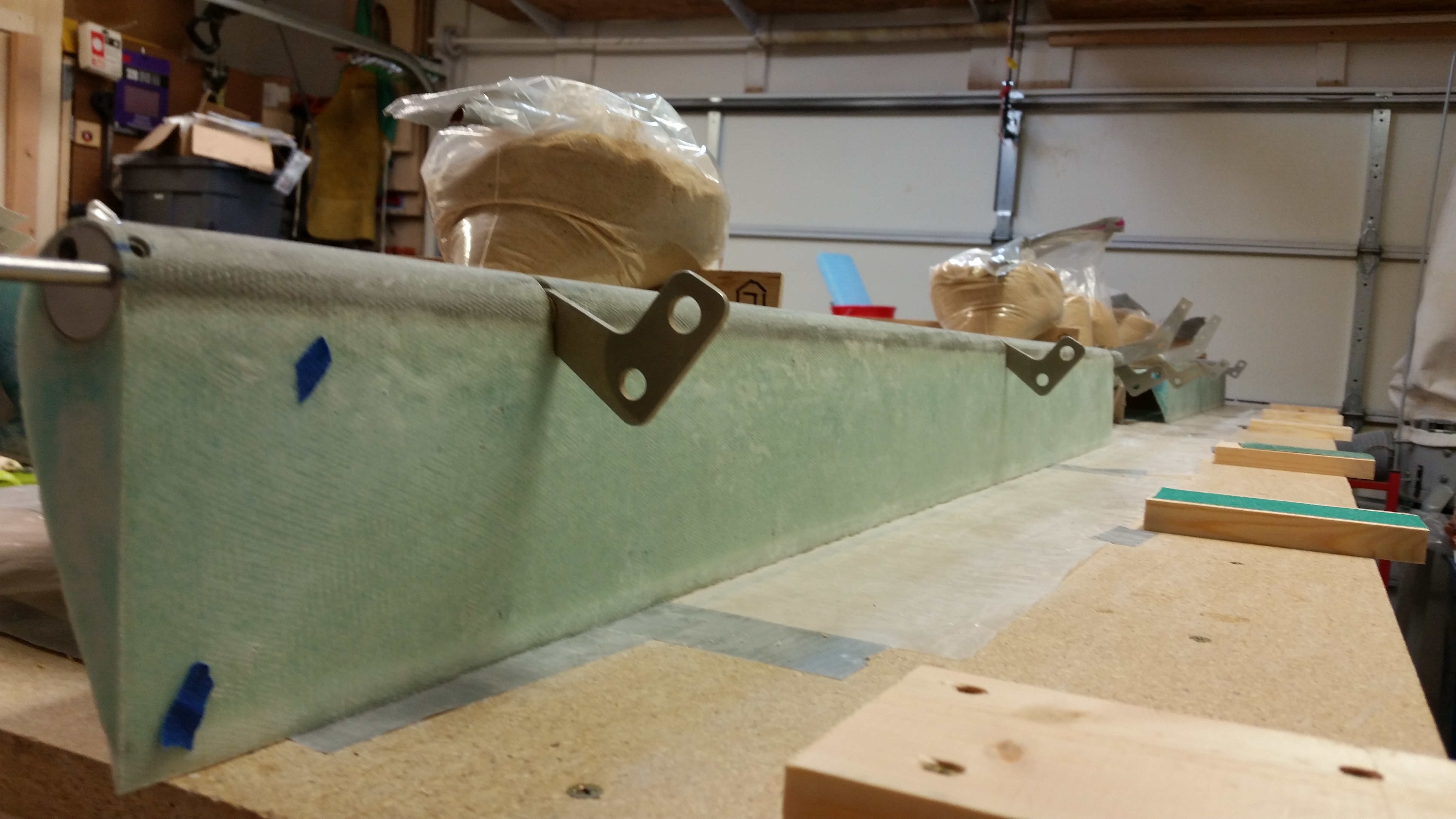
Here are the elevators, each cut to length, mocked up & temporarily attached to center spool tube assembly. I double checked all the lengths & dimensions, and it all looked good.
A long view . . .
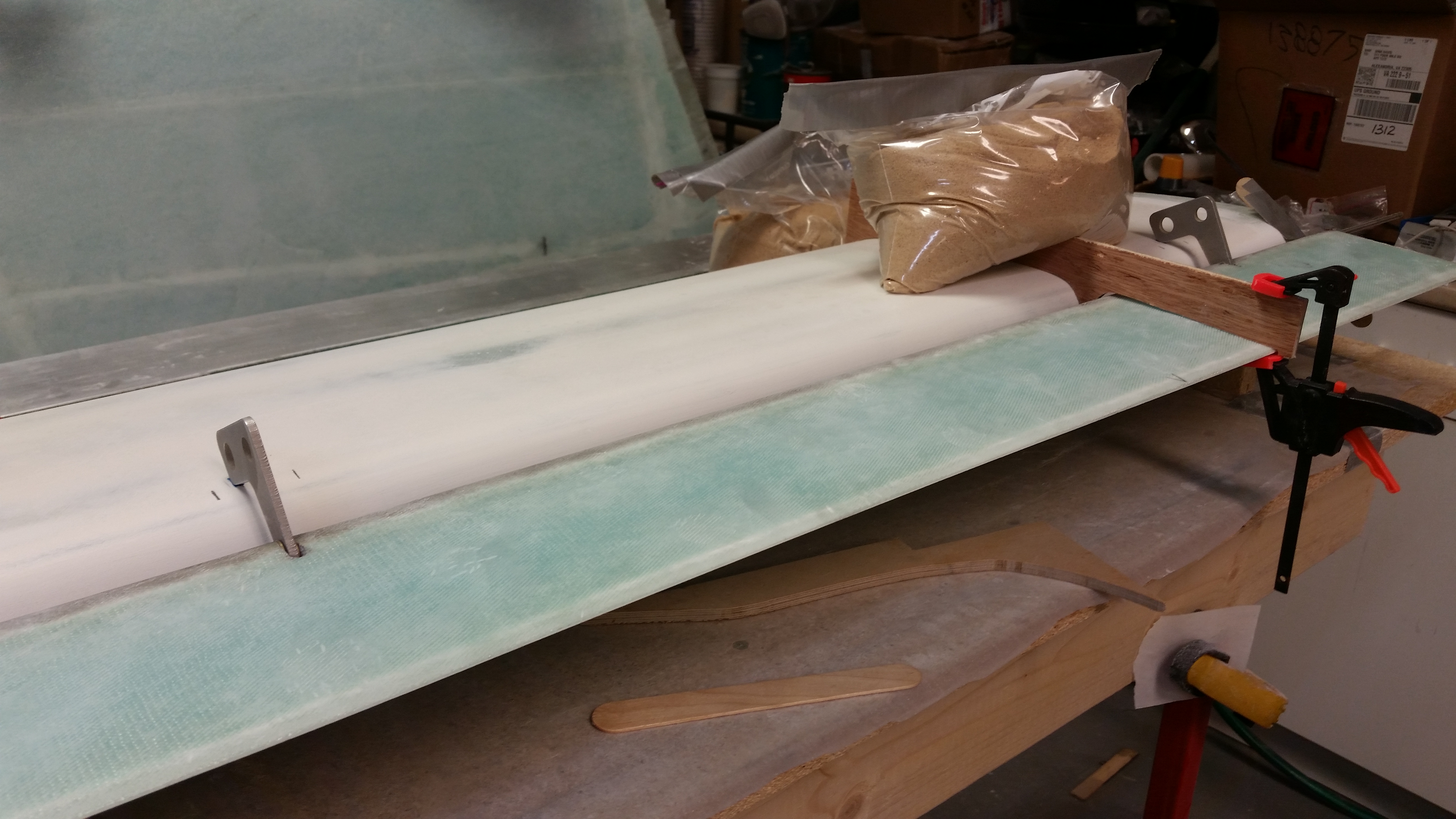
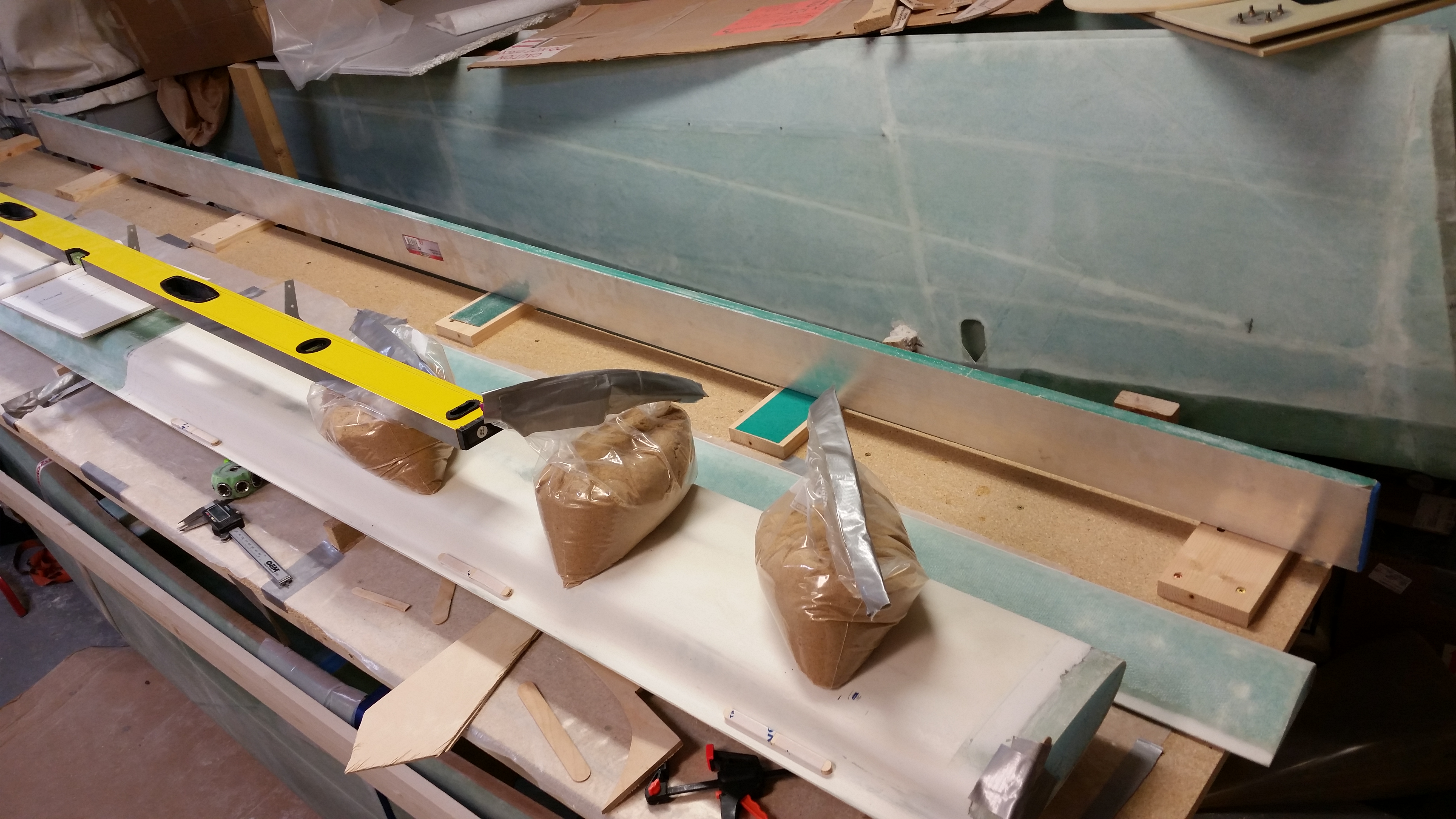
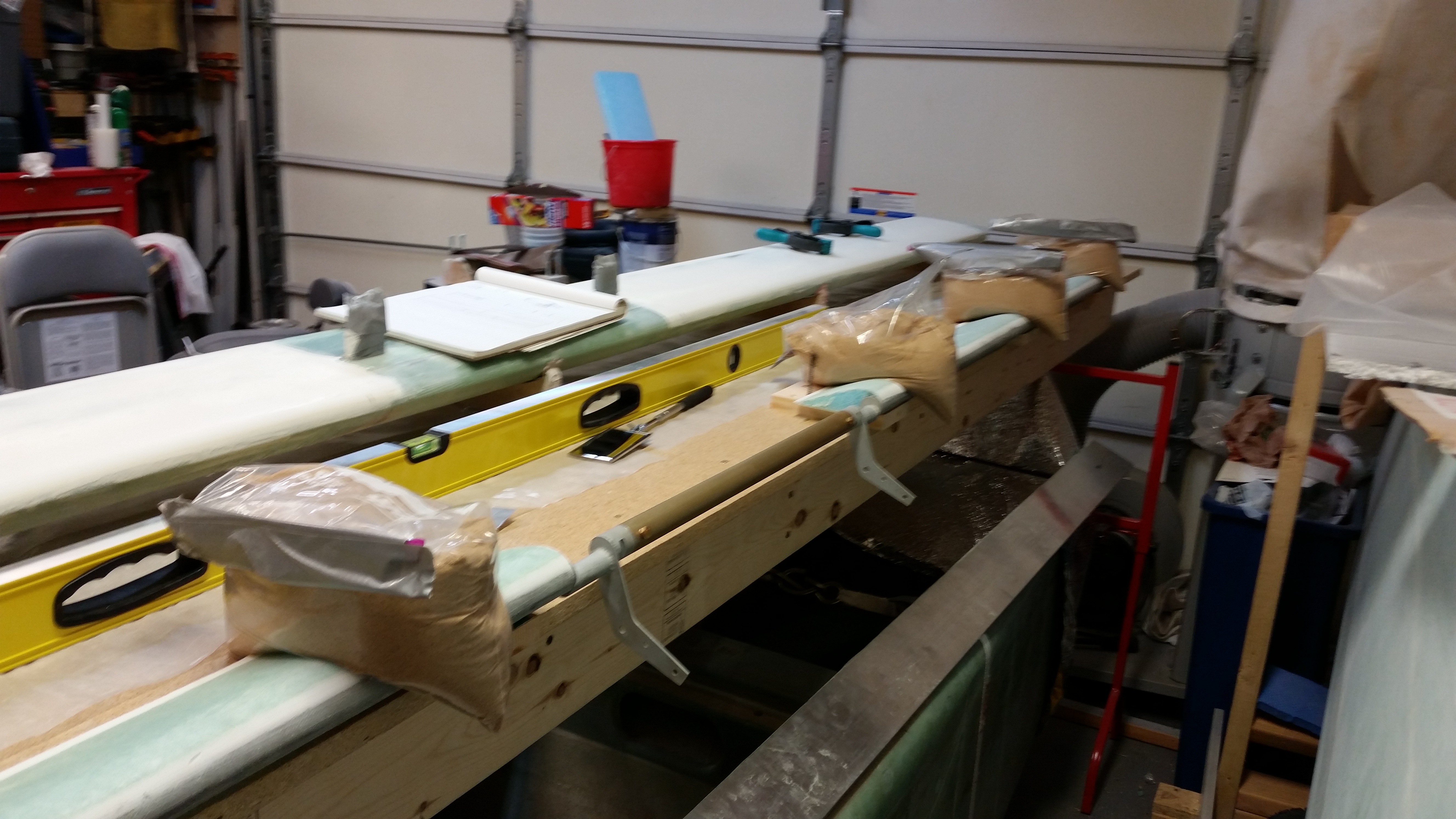
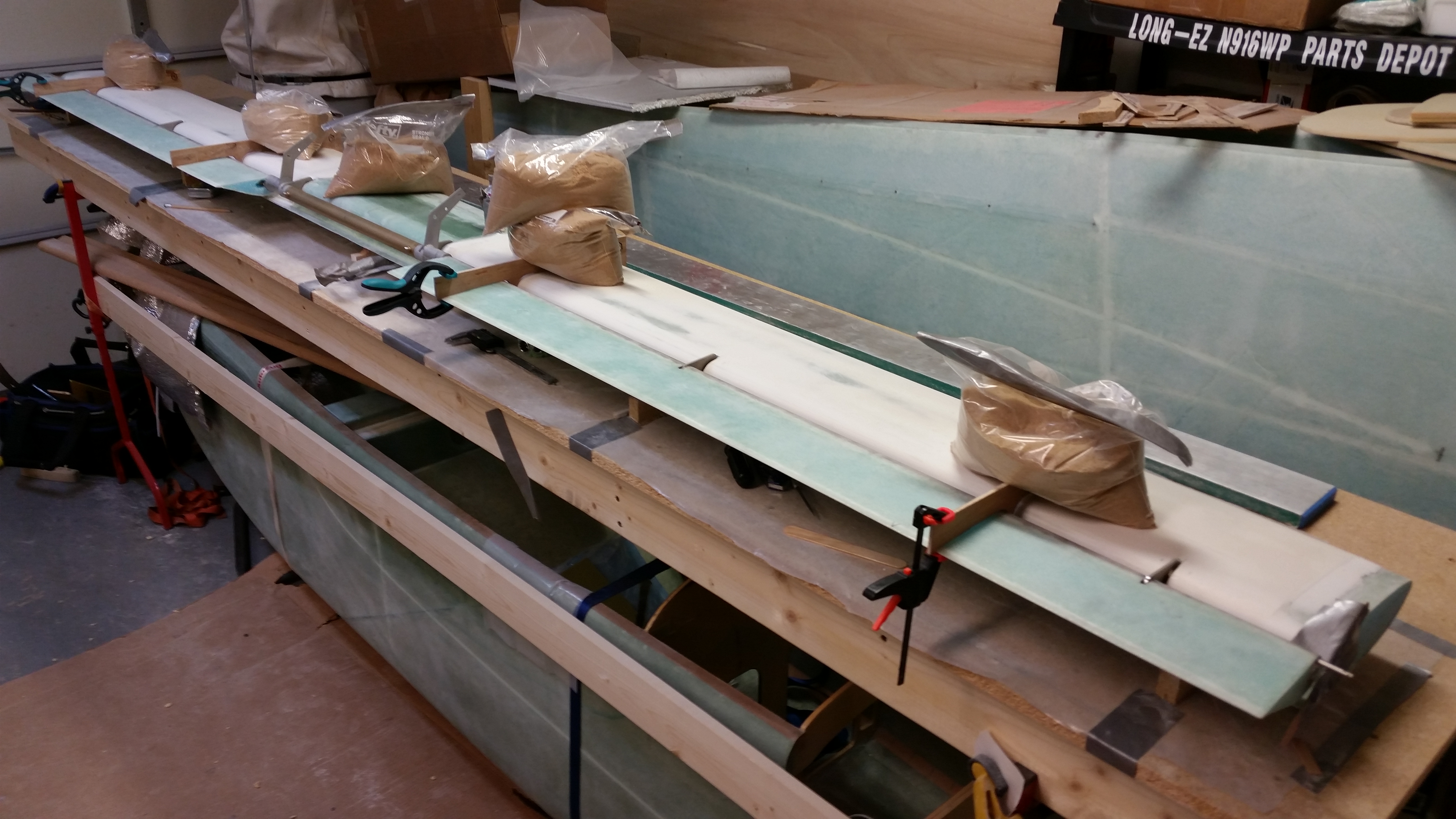
I then hunted around for a decent sized board–moreover, one that was straight!– to cut for the jig mounting bases for the elevators to sit on while they are bolted to the torque offsets on the end of the center spool tube. I cut a pine board I had into 6″ lengths and then screwed them to the work bench, all with a 1″ overhang.

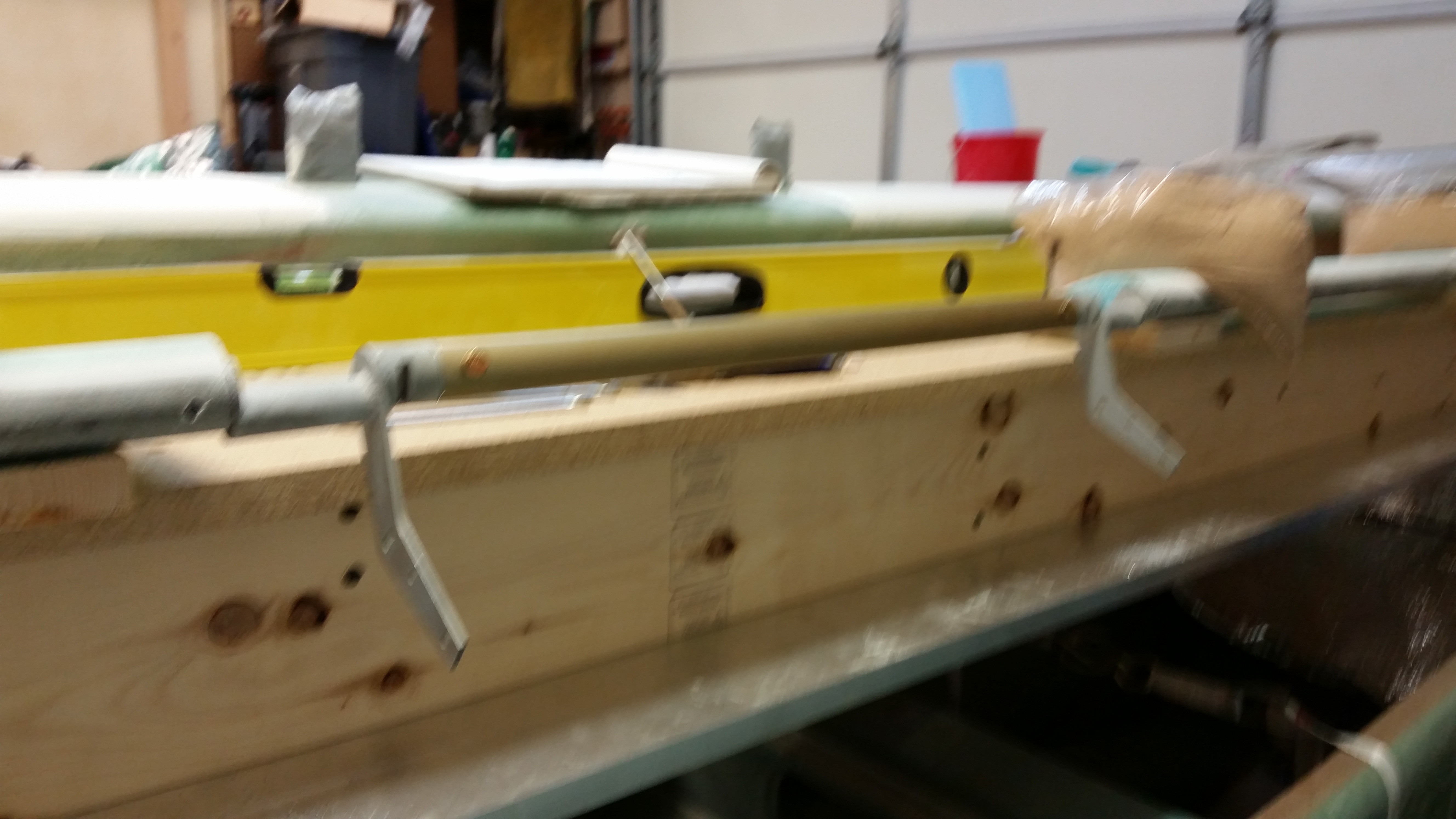
I then checked the entire length for straight & level with my German aluminum straight board. My second and third jig was a little low, so after hunting around a bit for something to fill the gap, I got the idea to recycle a piece of 80-grit PSA sandpaper (sticky backed) to use on the second jig, and on the third jig a piece of 36 grit. Those did the trick and the mounting jigs were all straight and level!
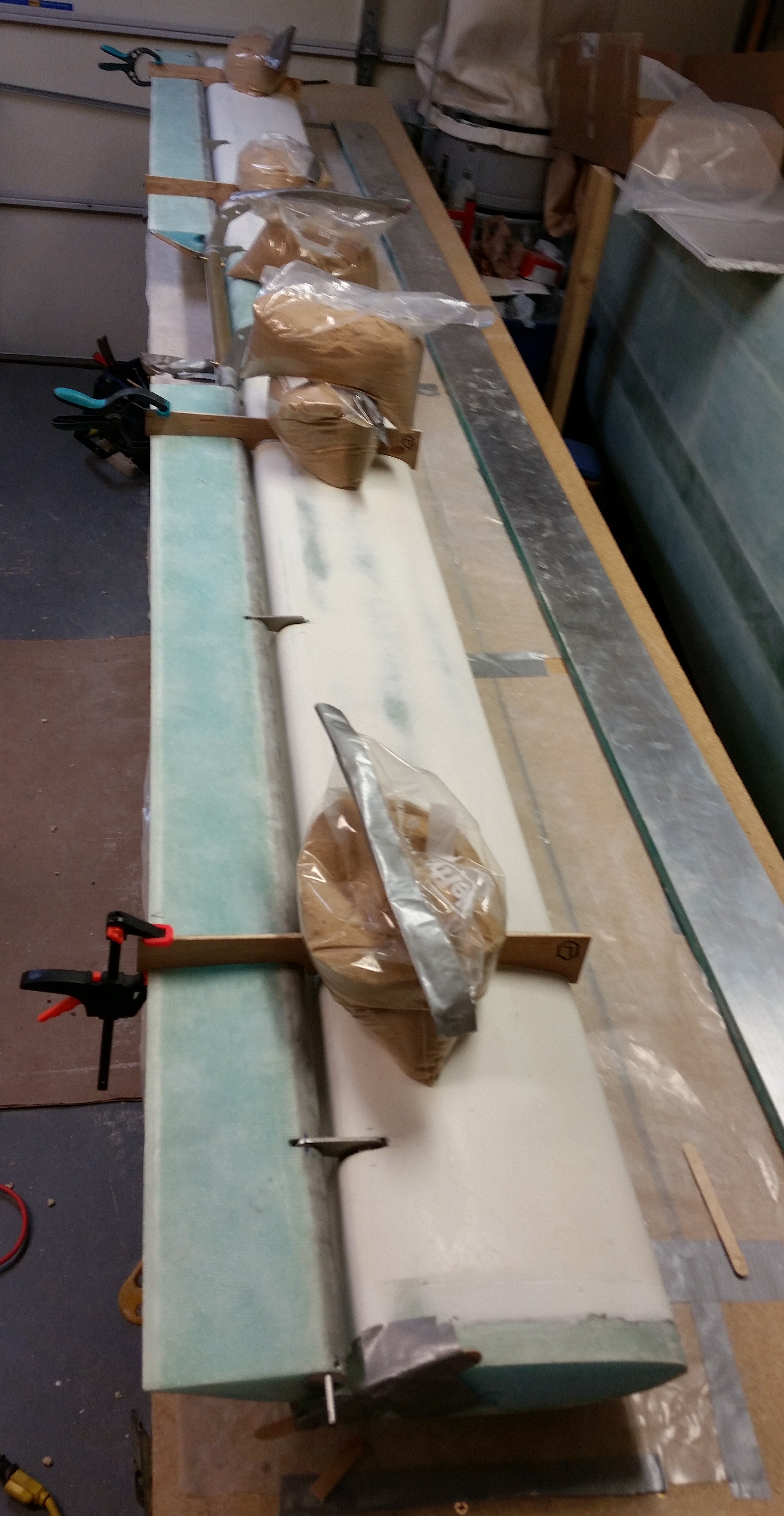
I then mounted the elevators to the center spool tube assembly & torque offsets. Since there is a hinge that goes into each torque offset assembly, then the 3/16″ stainless steel hinge pin goes all the way into the torque offset. This really makes it easy to figure out the angle of torque offset arms because the hinge pin must be installed. In other words, if I’m off, it won’t be by much at all!
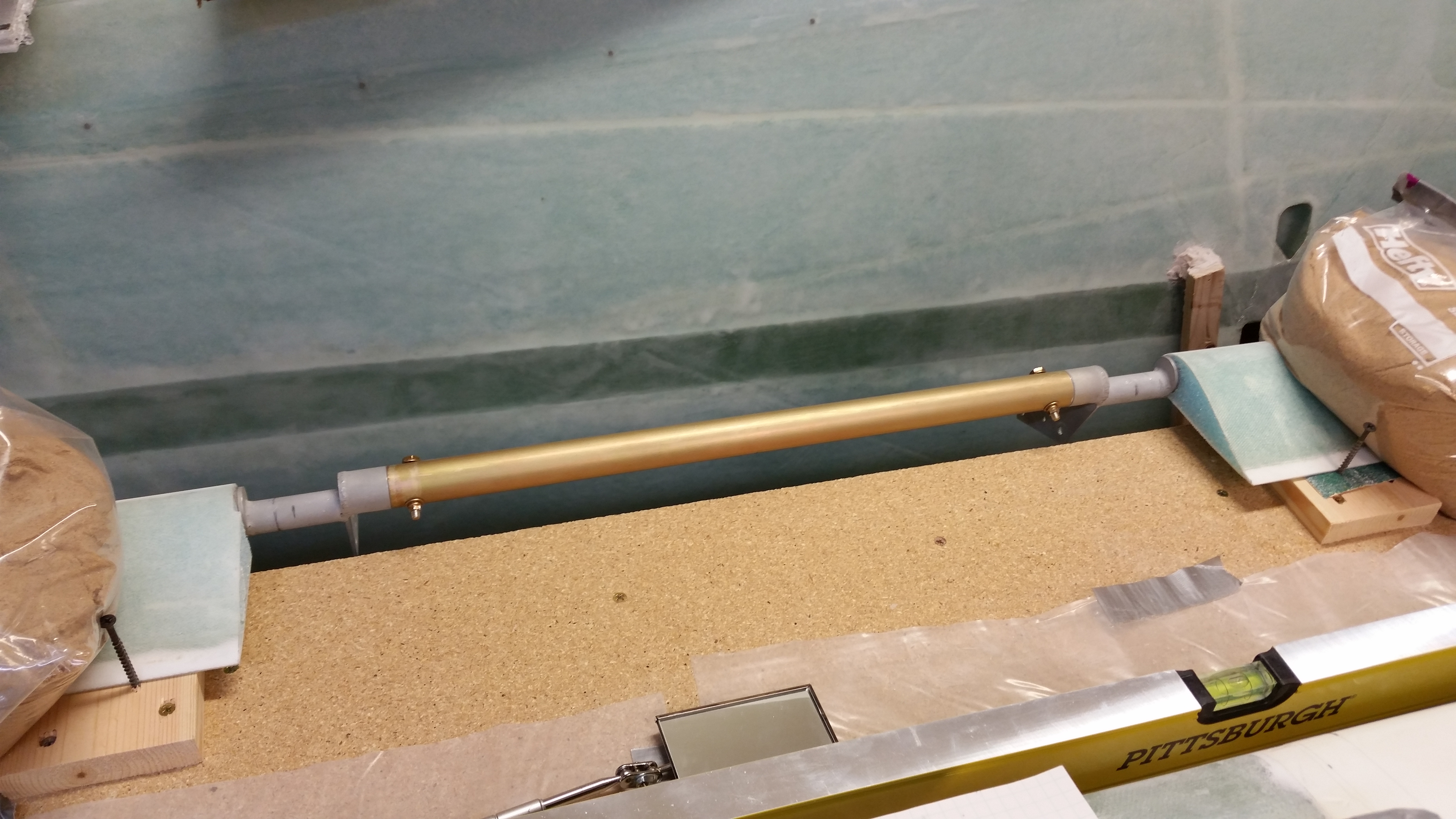
I marked up a popsicle stick with a line at 1.6″ to set the distance between the back edge of each jig to the TE of the elevators. As I measured each TE gap on the jigs, I weighed down the elevator at that jig. I then installed the 3/16″ stainless steel hinge pin into each side [NOTE: If I had been thinking more proactively, at this point I would have installed the hinges to avoid having to install them later and thus keep from having to manipulate the entire assembly as one complete unit].
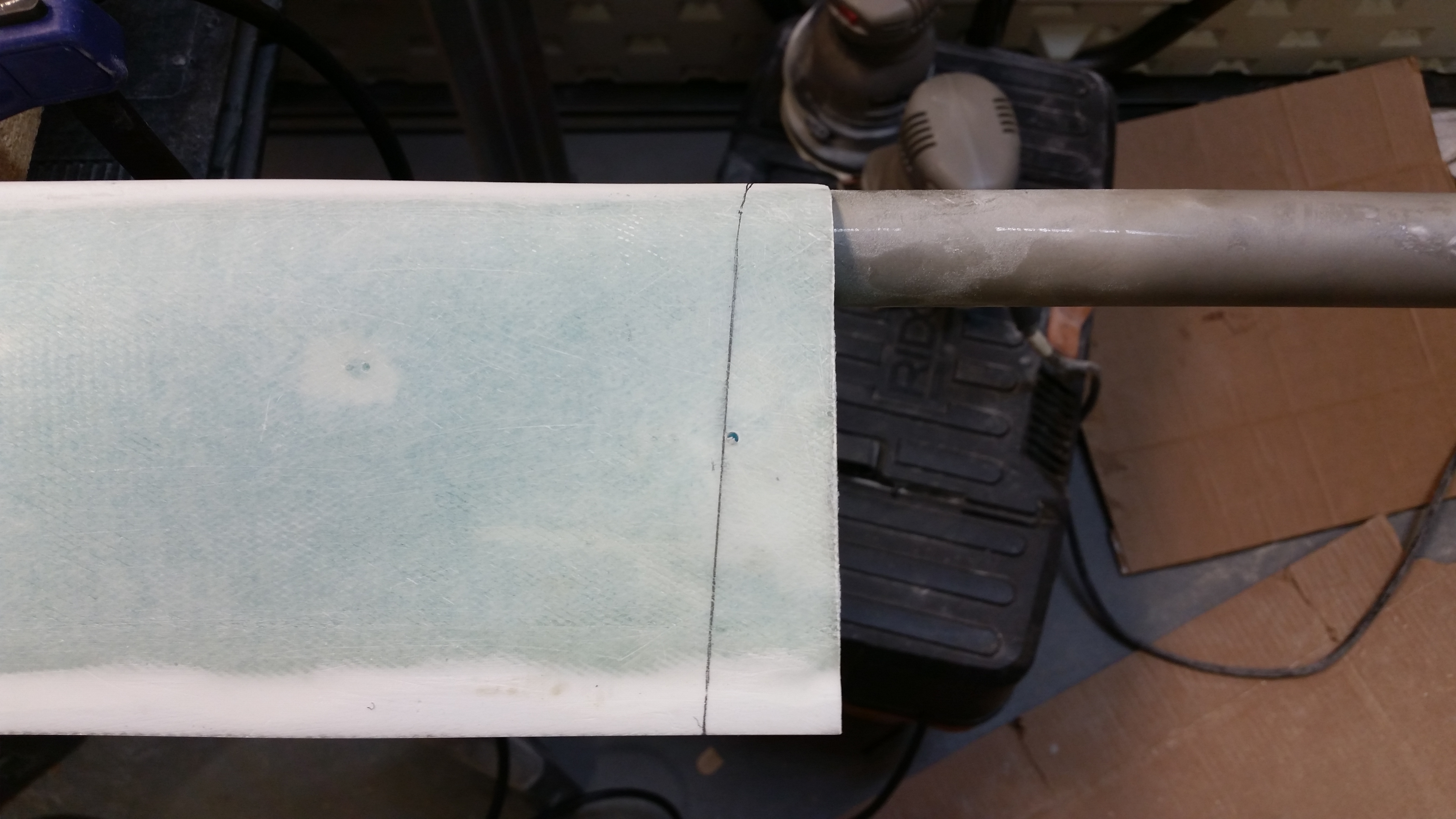
Pardon the fuzzy pic below, but if you look closely at the root of each elevator you’ll see that I’ve drilled the #12 hole on each side.
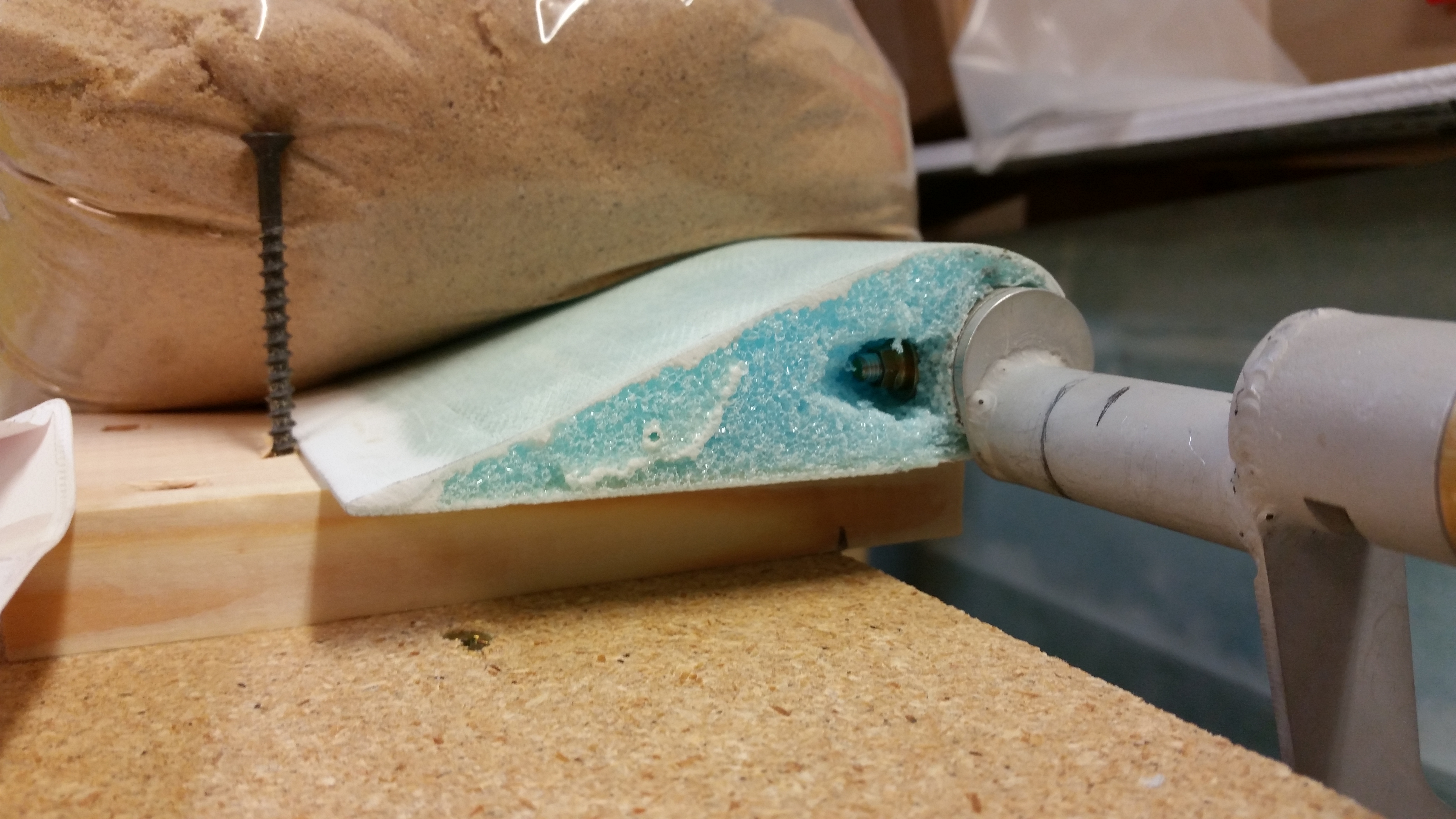
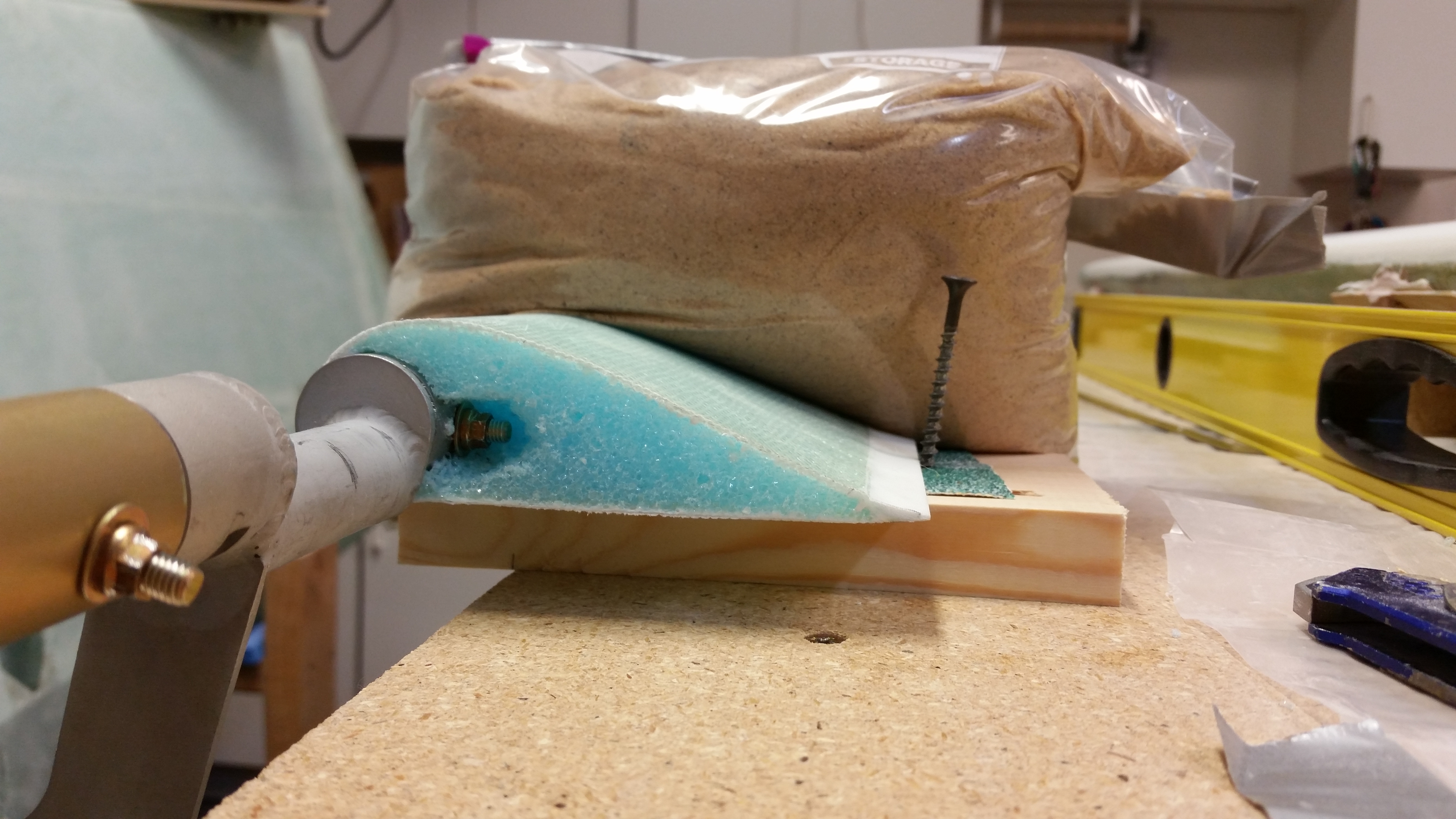
Here’s a shot of each side of both the inboard foam edge of the elevator, and the screw I placed right behind the trailing edge of each elevator to keep the elevator from shifting away from the drill bit as I drilled the holes.
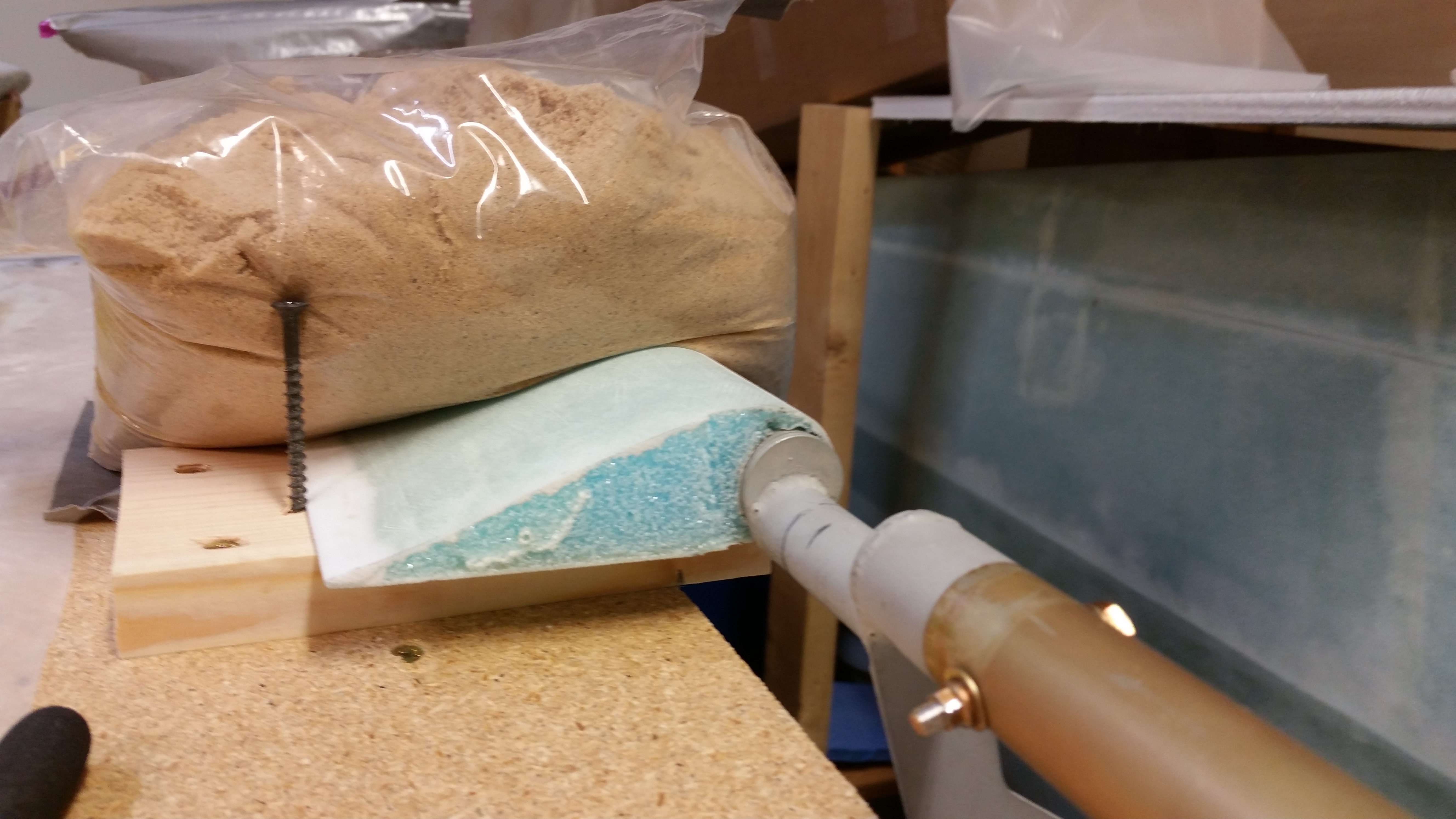
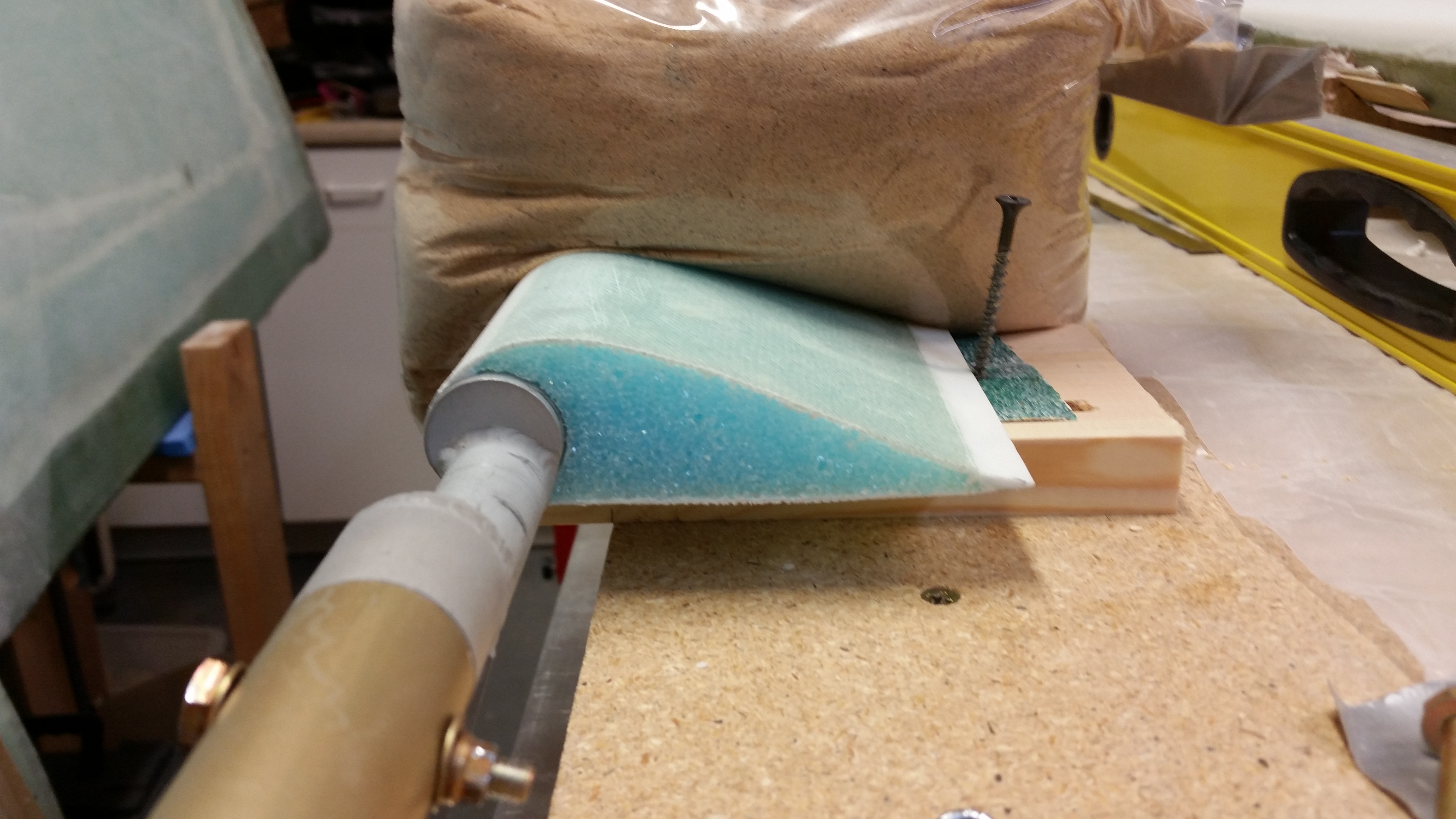
And here’s pretty much the same views only this time the bolt holding the elevator to the torque tube end is visible inside the foam.
The next step was to get the elevator hinge slots marked up for cutting.

I then cut the slots for the hinges and dug out the foam down to the top side glass.

After vacuuming out the hinge slots in the foam hard points embedded inside the canard, I pulled off the sandbags.

I then installed all 6 hinges with their associated washers.
I then reset the “L” brackets, secured them in place with sandbags, and remounted the elevator-spool tube-torque tube assembly to the canard. I slid the hinges into the hinge slots to check their fit, which will definitely need some tweaking.
 Next I’ll be working–probably all day long–to get the elevators situated correctly on the canard and then the hinges floxed into place inside the hinge slots.