There are a number of major tasks in building a Long-EZ that remind me of that aged old question: “How do you eat an elephant?” And of course the answer is: “One bite at a time!” Ahhh, true words in the realm of airplane building. Thus it is so with mounting the elevators onto the canard.
My first task today was to review the plans and my notes. I then went out to the garage and assessed how the elevators were looking in their mocked-upped state on the canard. It was immediately clear to me that the bottom edge of each of the elevator hinge bracket slots would have to be lowered. These are the slots that I cut into the foam hard points on the canard last night.
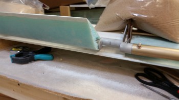
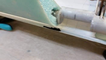
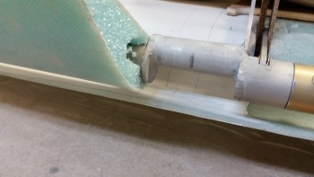
After dropping the aft edge of each hinge slot, ensuring that I had a glass surface in the bottom of each slot, cleaning up the foam bits, and vacuuming the holes out, I remounted the elevator assembly to take a look. Ah, much better! The elevators were aligning much better and the gap between the elevators and the canard looked good, at least initially. I stole a page from my good friend Dave Berenholtz’s build book by using shims to lock the hinges in place so I was free to play with the elevator movement and really get a good idea of my elevator travel situation.
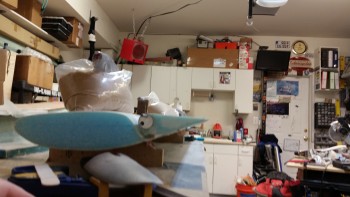
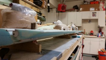
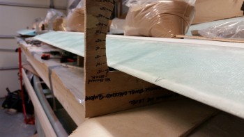
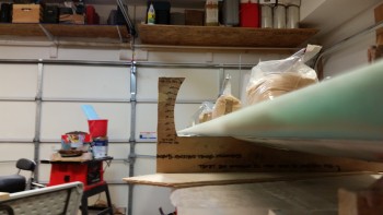
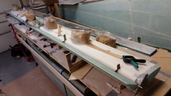
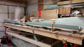
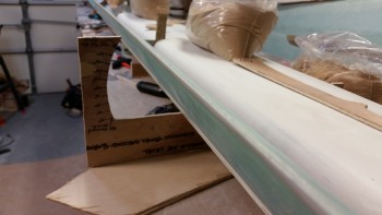
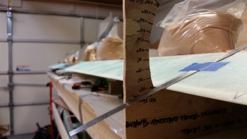
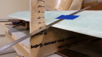
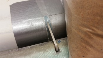
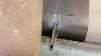
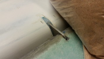
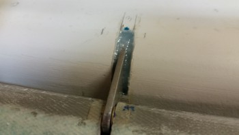
I checked the alignment between the two elevators to see if I had any issues. Sighting down the TE of the elevators I was quite pleased that it looked like the TE was on rails as far as the alignment between the left & right elevator. I tried to get a shot of it as best I could, thus the 2 pics below:
Before I went any further I gave Mike at Feather Light a call about the Canard TE and the interface gap between the canard and elevators. Since Feather Light cut my canard & elevator cores, I wanted to discuss my slightly high TE as compared to the template in the Roncz canard plans. My TE is just angled slightly less downward as it slopes aft, which makes the ENTIRE TE measure about 0.07″ higher than the diagram in the Roncz canard plans. Since the fishtail on any aerodynamic surface is glassed first, this wouldn’t be an issue of my doing since I merely glassed the bottom of the canard first, which included the already shaped TE fishtail. After a good talk with Mike I felt comfortable in keeping my gap wedges at 0.23″ thick, since this would: A) put the bottom of the elevators ever so slightly toward their original position as per plans, and more importantly B) still give me an appropriate gap, especially once the finish and paint is complete. So, I pulled the trigger & moved on!
I then mounted the elevator angle template to see how I was doing on the elevator travel angles. Of course the long pole in the tent when mounting the elevators is to ensure there’s enough up-elevator travel… otherwise known as the “ever-elusive 15° up travel,” or something clever like that!
As you can see from the pics below I was getting somewhere around a 13.5°± up travel. Of course this is already within specs as 12.5° up travel is the bare minimum, but since I was just starting out, I figured I could easily squeeze another degree from somewhere & get this thing close to 15°!
And to be clear, getting the max 15° travel really isn’t a pride issue. I’m seriously just trying to be proactive since once the finish & paint go on, as well as the 2 plies of UNI for the outboard elevator weight, who knows how much that will reduce my up elevator travel. So I want all I can get from the start.
I found the culprit at the very inboard edge of the right elevator. I locked the elevators in the up position by placing a sandbag on the torque offset arm (you can see it in the pic below) and then started sanding away with some 36 grit.
After a bit of sanding I tried the up travel again and only saw a slight improvement. So I checked the gaps and position of the elevator assemblies, and then pinpointed the exact spot that was causing the issue. I took a Sharpie and marked the offending area and hit it with another round of 36 grit, as you can see in the second pic below.
I figured while I had the elevator locked in the “up” position (of course it’s really in the down position) I would grab a couple shots.
Clearly I have no issue with my down elevator travel!
And now I’m good on my up elevator travel! I always say that there’s no problem in this world that can’t be fixed with 36-grit sandpaper . . . ha!
I moved the elevator degree template over to the other side and am still getting about 14.7° up travel. Not sure why the difference since I rechecked my gaps, my “L” template spacings, and left/right elevator TE alignment. Could just be a combination of factors, but since everything else is lining up well, I’m calling this good.
A thought I had on the inboard problem area causing the limit in up elevator travel is that if I go with a decent fairing at the elevator root then I could simply eliminate the problem area. I’ll keep that in my back pocket in case I need it later on.
Here I’m simply comparing the “Zero” elevator in trail on the degree template vs. the zero trail on the “L” template. I already knew there was a very slight gap on the “L” templates towards the TE of the elevators when I checked them against the Roncz canard plans diagrams, but I was curious how these matched up. They’re only slightly different, but close enough to get the kinks worked out when I rig the elevator control system later on.
And here’s a wide-angle shot of the elevators in the up position.
I spent about 45 minutes checking the elevators and spool tube assembly for alignment. I took out my über gut German aluminum straight board to check the TE alignment. My right elevator was just a tad off with the inboard more aft than the outboard end. When I checked my “L” template alignments, I realized that perhaps working the elevator up & down had caused the right inboard hinge point to be off. So I went back and rechecked every gap spacer and “L” template for elevator vs canard spacing, and then did a TE check again. I checked my elevator travel again and it all looked great.
I stole yet another play out of Dave Berenholtz’s playbook and instead of floxing all the hinges at the same time, I wanted to ensure that I install the elevators in one calculated step at a time. Thus, I taped the areas around each of the two middle hinges of the left and right elevators, respectively as you can see below. This gives me a midpoint fulcrum, if you will, to ensure that the the outboard and inboard hinge areas are perfectly set when I flox them into place.
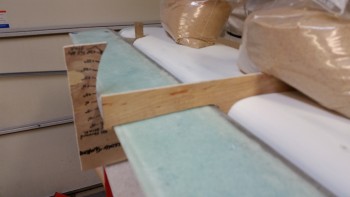
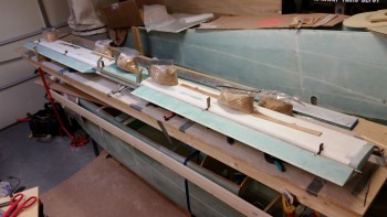
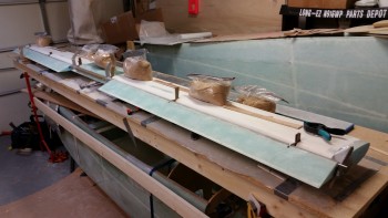
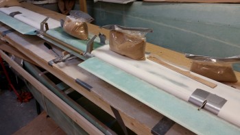
Also, I noticed that the gap between elevator and canard TE in the middle of each elevator is about 30 thou greater than each end of the elevator. After looking at this for a bit, I concluded that it’s most likely hot wire drag when they cut the foam cores. I point this out because I also noticed that if I just added the slightest bit of pressure on top of the elevator (as it sits now) that the gap almost completely closes. I then tried adding a little weight to the midpoint areas of each elevator and sighting the TE from end to end: no discernible negative affect on TE alignment. Thus, in each pic below you’ll note that there’s a sandbag next to each middle hinge point as the hinge is getting floxed into the slots on the canard. And again, we’re talking maybe a total movement of 15-20 thou when all is said and done, so I don’t see the hinge swing geometry getting all wonky either.
Fast forward 5 hours later and here are the two midpoint elevator hinges mounted in the canard, after I cleaned them up.
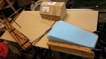
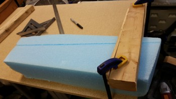
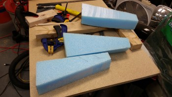
While the midpoint hinges’ flox cures I attempted to remain productive the rest of the evening by cutting the blue foam wedges for the Roncz canard swoosh tips. I figured the easiest, cleanest way to cut the blue foam was using the hot wire cutter.
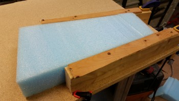
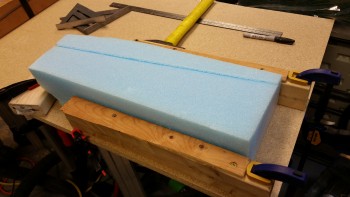
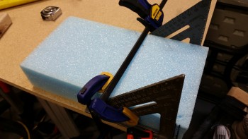
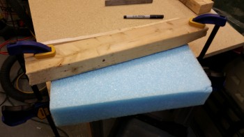
I added a 1/4″ scrap runner to the top of two 17″ long 2×3’s that I cut. Of course the 2×3’s are, interestingly enough, 2-1/2″ wide. I then clamped the 2×3’s on each side of the first piece of blue foam and tested it out.
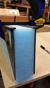
And here’s the result. Not bad, but the hot wire cutter definitely felt “dull.”
I continued cutting the first blue foam piece to get the swoosh tip piece as per the plans dimensions.
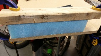
And then I grabbed another piece of foam to make the second blue foam canard swoosh tip wedge piece.
Funny, but if I had started with the first piece of foam, I would have ended up with the two swoosh tips that I needed. Oh well, now I have a spare!
The next step will be to finalize the floxing in of the elevator hinges into the canard hinge slots. Since I won’t mess with the elevators or canard for a full 24 hours after I set the hinges, I’ll be working on getting the top canard contour “E” template traced and made into a canard top contour sanding block just as I did for the bottom. I’ll also find the pieces of UNI for the canard tips, locate and/or procure the plastic tubing for the canard tip elevator hinge pin bracket, etc.
Bottom line is that there is plenty of prep stuff to keep me busy while the elevator hinges flox cures.

