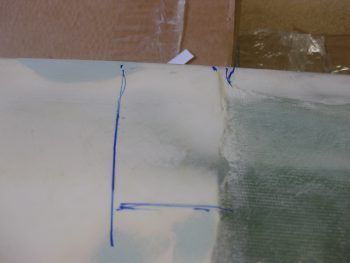
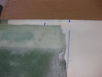
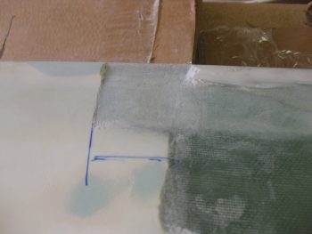
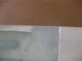
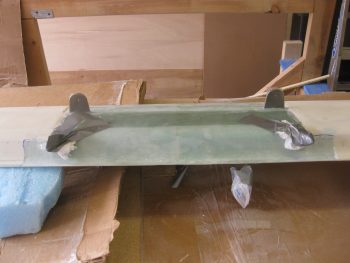
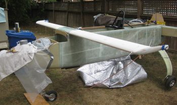
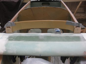
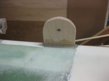
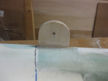
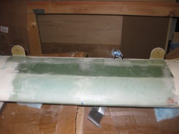
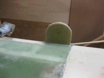
Today I started off clearing off the micro & finishing material from the top TE of the canard where the upper alignment tabs need to be glassed in. I marked the spots first, for the right side, then the left . . .
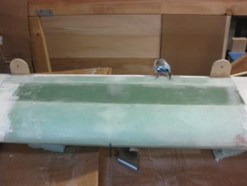
And then cleared out the finish and sanded it down in prep for 5 plies of BID.
Although I didn’t take any “before” pics, I then did the same thing for the bottom side of the canard. The alignment tabs will get 4 plies of BID on the aft/bottom side of the canard.
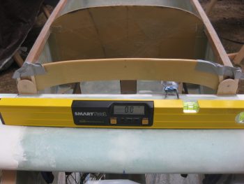
After checking the fuselage and spar to ensure all was still square, I then mounted the canard on the fuselage. It seemed after the rain yesterday that the airplane had settled a bit, and it may have ever so slightly. But my measurement across the aft ends of the longerons today revealed some spar-to-longeron mounting glass that was sticking up just a hair that would cause some erroneous level readings yesterday.
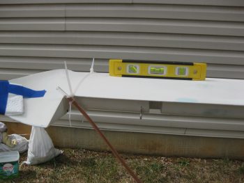
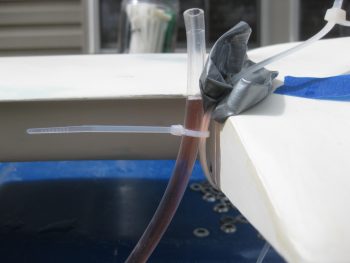
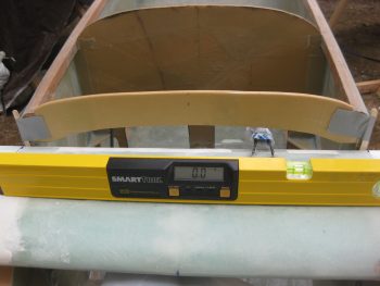
In addition, I used a very simple Side A-to-Side B water level on the canard today, as well as using levels to ensure that it is level from side to side.
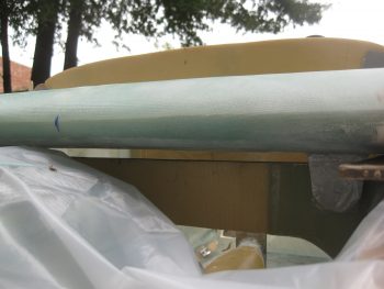
Here’s the right side water level showing it aligned with the canard TE.
I still had to shim up the right side about 0.160″ to get the canard level. A little more than my estimated 1/8″ required to offset my twisted fuselage, but I’ll live with it vs. rebuilding my fuselage!
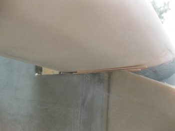
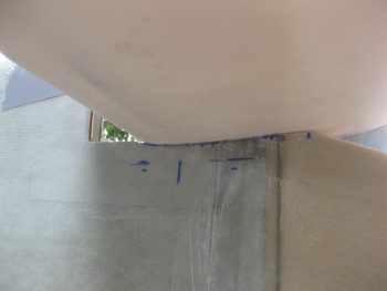
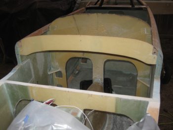
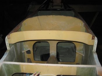
I wanted to show a pic of the gap between the canard and F22. Today I plan on minimizing that gap by contouring the sides of the fuselage to match the bottom-side canard profile.
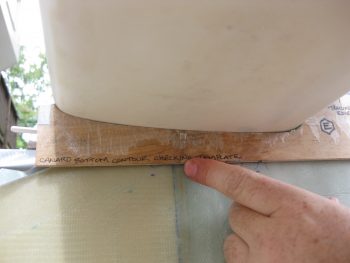
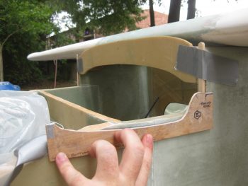
In fact, I dug out Template “E” to help me do just that. First, I measure the normal lower profile of the canard, making a few alignment marks along the bottom edge of Template “E”.
Then, I figured out how much I needed to lower the left side canard and marked those lines below the bottom edge line of Template “E”.
I then moved the canard off the F22 “shelf” so that I could have access to sand out the bottom F22 profile. This happened at least 20 times today, trial and error being the order of the day!
With the lower marks in place, I simply matched the lower straight edge of Template “E” to the lower marks and then marked along the top edge of it which gave me the correct contour I needed for the bottom of the canard.
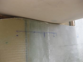
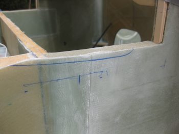
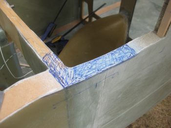
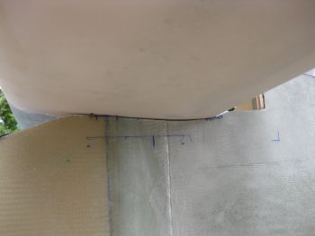
I then sanded down a significant portion of the area above the profile line above, and then kept checking for the high points (as shown below)… marked those and proceeded to sand them… with prejudice! Again, this process was repeated countless times!
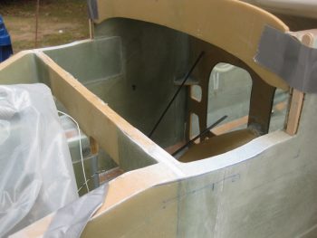
Here’s a shot of the fuselage sidewall cutouts. Notice the left is much deeper than the right sidewall. Which accounts for my lopsided fuselage (ahhh, the sins of the past….).
Here’s a couple more shots with the canard in place, from below.
As I did hundreds of times today, I then rechecked the level on the top of the canard. I was having a devil of a time getting the canard to stay level whenever I tweaked the incidence. Of course the Roncz canard mounts with the lower tabs at an angle (unlike the GU canard), so keeping the bottom tabs tight wasn’t allowing me to get the canard Leading Edge (LE) nose up for the proper incidence. The whole herding cats thing was in full swing here, so I decided to minimize my variables and work with the known quantities I had on hand.
To keep the lower mounting tabs clamped, but then still be able to dial in my incidence by getting the canard TE down –thus, in essence the LE up– I decided to use my upper alignment tabs to do just that, align the canard! So with some trial & error, and the main mounting tabs secured with clamps, I was able to use the height of the upper alignment tabs to dial in the correct incidence WHILE at the same time keeping correct sweep and level.
Of course this is NOT the order that the plans have you do all this, since in the plans you drill a #10 pilot hole through the lower tabs first, then mount the upper alignment tabs later. But the original plans are dealing with a straight-flat-bottomed GU canard that required no contouring of the fuselage sides. I tried to prognosticate any future issues by doing it this way, and I couldn’t think of anything that would come back to bite me, so I proceeded to drill, trim & mount the Birch plywood (vs foam) for the upper canard alignment tabs.
That kept the canard sweep & the level dialed in. But I of course re-checked both to ensure all was good!
Continuing on with my working the known variables theme, I went ahead and glassed the front mating face of F28 to dial in my sweep with the newly mounted upper alignment tabs. I figure I’d work the canard install elements in the same way they are presented in Chapter 12 of the plans: SWEEP ⇒ LEVEL ⇒ INCIDENCE.
It may be a bit difficult to see in the pic below, but I then cut wedges in the foam sidewall uprights that are adjacent to F28.
I then filled these foam wedges with flocro just prior to laying up 12 plies of BID on the left side (remember, I need to bring this side face out 0.155″) and then laid up one ply BID on the right side. I was going to only layup 11 plies of BID on the left side, but went ahead and added one more so that I could the glass the right side with 1 ply of BID as well.
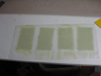
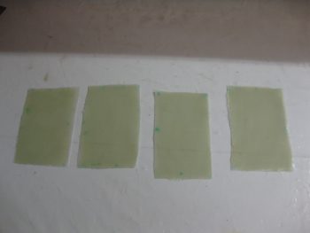
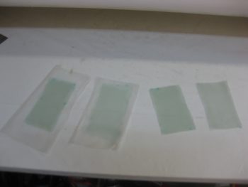
I had already wetted the 12 plies (in 4 sets 3 plies) of BID out before filling in the foam with flocro, so when I got back into the shop I merely squeegeed out the excess epoxy.
I then cut each set of the 3 plies of BID in prep for layup.
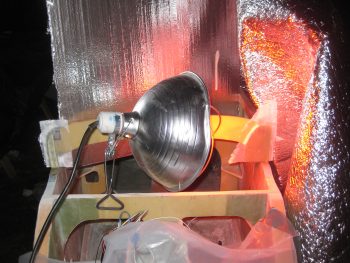
Here’s a shot of the heat lamp on the 12 ply BID layup. Let’s just say that it cured fairly quickly!
With the F28 bulkhead spacers in place, I then set my sights on glassing the front side of the upper alignment tabs with 5 plies of BID each. I do have to state that my 5 min glue must be old because it was still a bit rubbery even after about 25 min. I’m only going to layup the front side BID so that if need be I can heat up the tabs and move them forward or aft. Not an optimal way of doing this most likely, but I really saw no other way of dialing in the incidence without spending an enormous amount of time making wedges for the lower mounting tabs…which just didn’t seem nearly as efficient as doing it this way.
I sanded away the gummy 5 min epoxy on both tabs…
Then wetted out 2 sets of 3-ply BID and 2 sets of 2-ply BID to give me a total of 5 plies for the layups for both the left & right tabs.
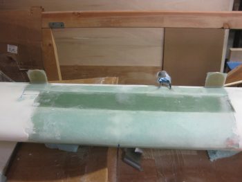
I then laid up the forward tab faces with 5 plies of BID, after troweling in some dry flox fillets in the mating corners. I then peel plied the lower, horizontal part of the layup for a smooth transition into the canard top surface.
After a couple of hours, I then razor trimmed the upper tab glass.
Here’s a shot of the left upper tab after I razor trimmed it.
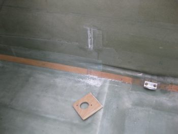
I did do one thing today not canard related: I used my Fein saw to remove the CS118 plate in the back seat in prep for moving the control stick mount just a hair inboard!
Tomorrow I plan on moving out as much as possible to get the canard mounted to the fuselage.
Much to do before Rough River!
