
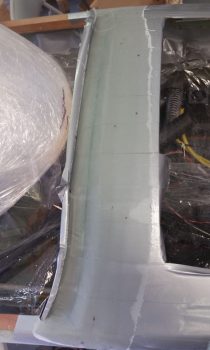
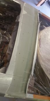
I started off today checking my aft nose/avionics top deck actual glare shield layup. I pulled the peel ply and it looked fine. I’ll need to do some aggressive sanding to knock down a lump & bump here and there, but overall I’m very pleased with the results.
Today I wanted to take a big swipe at getting the internal components installation squared away on the GIB headrest before the structure gets glassed into place. Yes, I know! A bit of a rabbit hole to be sure, but yet just another sequencing thing that if done now will make the build progress much easier in the long run. Definitely worth a 2-day detour in the grand scheme of things.
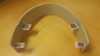
I started by checking, cross checking and double checking a myriad of final layout measurements. I then cut out 4 each 1/16″ thick phenolic tabs for mounting aluminum angle cross-headrest mounts. I then measured, marked and cut slots for the phenolic mounting tabs into the inner surface skin of the headrest. I dug out the foam so that the outboard edge of each mounting tab sat flush against the interior surface of the outer skin.
Once all looked good, I sanded both sides of each phenolic mounting tab rough, flocro’d them into place and then laid up 2 plies of BID on the front side of each tab, and 1 ply on the aft side of each tab. I then peel plied the layups, and after the tabs looked like they were set in their final position I took off to grab some supplies for glassing the nose and canopy, and to run a couple of errands (they weren’t set completely… and a couple moved a small amount on me).
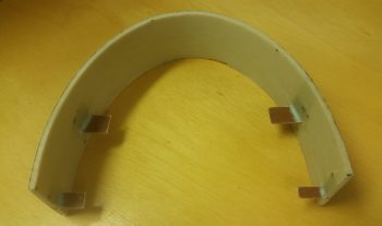
A couple of hours later, after I returned from my mini-sojourn out, I pulled the peel ply and knife trimmed the glass edges.
I then spent the next 5+ hours finalizing the position of both angled aluminum mounting brackets, the respective components and the mounting bolt positions as I slowly drilled and riveted a BUNCH of nutplates into place. Here you can see the backbone of the mounting setup in the GIB headrest: the top and bottom 1/16″ aluminum angle.
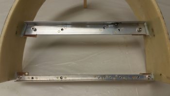
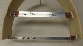
Here’s an aft view of the top and bottom aluminum angle mounting brackets with a bunch of nutplates riveted into place. Quite obvious I guess, but for me personally I don’t want to mess around with the initially easier task of simply drilling a hole then using a nut & bolt to hold a component into place… I want to remove the nut from the equation and simply have to worry about the mounting bolt and that’s it.
Speaking of bolts. Since the access to the bolts around a good many of these components is very restricted, I opted to go with hex cap head screws that use an allen key for installation/removal. Maybe it’s just me (I’m sure it often is!) but driving small diameter bolts/screws into nutplate assemblies with a screwdriver is just not an optimized endeavor and the amount of pressure required to avoid stripping the phillips portion of the screw head borders on just plain silly.
After getting the first round of #8 and #10 nutplates riveted into place, I then did a test mount of a bunch of the internal GIB headrest devices. Note that this round of components all sit just forward of the two firewall face mounted MAP sensor boxes.
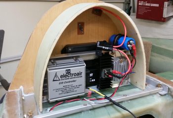
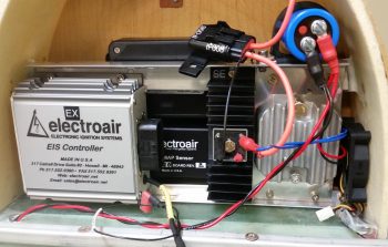
The components installed so far are as follows. Back row: GRT MAP sensor (top) and Electroair EI MAP sensor (bottom). Front row (l to r): Electroair EI controller, SD-8 backup alternator self excitation module (black heat sink), SD-8 voltage regulator mounted on 0.040″ thick heat sink plate, and SD-8 capacitor (big blue D-cell battery looking thing).
In the next pic after this one below I set the intake cooling fan in place, on the left (aircraft) side of the headrest next to SD-8 voltage regulator. The smaller exhaust fan will be installed at about the 10-11 O’clock position when viewing the headrest as below. Also, I clearly haven’t found a home yet for the rather robust inline 15 amp fuse (orange leads).
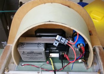
As you can see, it’s pretty tight quarters inside the ‘ol GIB headrest, and there still a number of components left to be jammed in there! If you’re good at games like ‘Where’s Waldo?’ then you may have noted that I added the cooling fan into the mix, in the lower right hand corner (of the pic)…. actual left hand corner of the headrest.
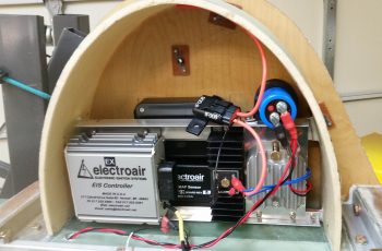
Here’s a view from a higher up angle . . . again note how it makes the headrest structure appear very round! Also, if you hadn’t noticed it already, take a look at the red & black twisted pair wire exiting the GIB headrest structure via the wire transit hole. Just an example of how the wires heading to the hell hole or points forward will exit the GIB headrest.
Engine specific wiring will exit through the firewall in one of two pass-thrus, situated in the respective lower aft corners of the GIB headrest . . . coincidentally, that’s why the MAP sensors are center mounted, to allow open wire paths to remain clear in both aft left and right sides corners of the GIB headrest.
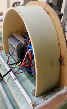
And a side view showing a bit of depth on the installed headrest components so far.
Tomorrow I’ll do round two of component install on the GIB headrest. I’m not really too concerned about the front cover since I’ll have access to glass in tabs, rivet nutplates or CAMLOC receptacles towards the front edge of the GIB headrest housing. Clearly the tabs I just installed and glassed in place would have been immeasurably more difficult if I had tried to do them with the headrest structure already installed. If all works out well tomorrow, I’ll most likely glass the GIB headrest structure in place atop its CS Spar perch and affixed to the front face of the firewall.
As stuff is curing I’ll also start doing some prep for both the nose and canopy structure builds.