
Like I said in last night’s blog, today was another focus on the GIB headrest.
I started by finely sanding the front edge of the headrest so that it was even around the front edge perimeter.
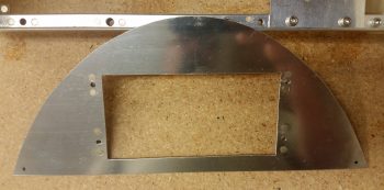
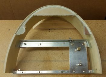
I then set about determining the size and configuration of the headrest’s top plate, which I cut out of 0.040″ thick 2024 aluminum plate. I then marked and cut a groove into the top half edge of the headrest that the top plate sits, and is mounted, recessed into… which is why I wanted the front perfectly “square” so that I could recess the top plate vertically, while the front of the headrest edge “leans” slightly aft being 3.9″ deep at the bottom base and 3.6″ deep at the top. If you’re wondering, the aft edge of the headrest is vertical and straight.
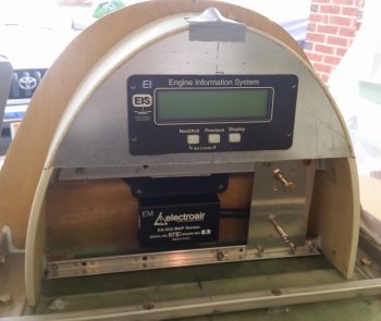
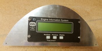
I then measured out, marked and cut a mounting hole for the GRT EIS4000 control unit. Of course I wanted to see how it looked, so I mocked it up in the headrest and set the headrest in in place.
I then knocked out riveting the four #6 nutplates for mounting the EIS4000 to the headrest top plate. I had to use the miniature version on the top holes so that the rivets wouldn’t peak out above the EIS4000’s mounting flange. I will be painting this top plate, but I still didn’t want to mess around with covering up any rivets if I don’t have to.
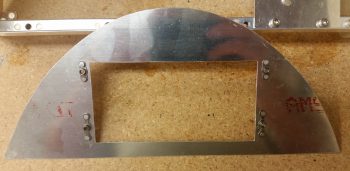
I then tried out the nutplates by test mounting the EIS4000 into the headrest top plate… thankfully it fit fine and no issues.
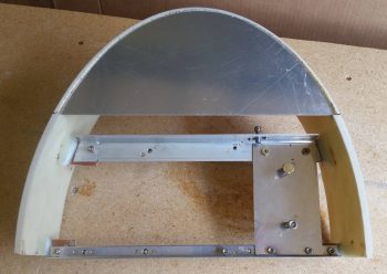
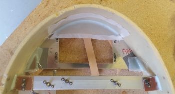
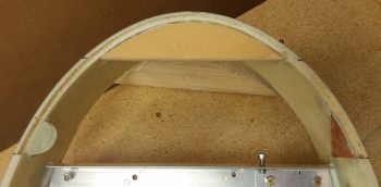
I then glassed a piece of 3/8″ foam into the top of the headrest arch, and some scrap pieces of phenolic and G10 –respectively– inside the upper headrest sidewalls . . . all which will serve as screw mounting points to secure the top plate to the headrest. I used 2 plies of BID and started the layups on the aft side of the screw mounting tabs. I taped up the top plate and used it as a type of jig to keep the tabs set at the right configuration, aligned evenly with the front edge of the recessed edge, not the front edge of the headrest.
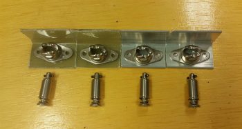
As the layups above cured, I got to work locating and cutting both glass and aluminum mounting tabs for the 4 CAMLOC receptacles that will be used to secure the headrest front cover (not top plate) in place.
A bit later I pulled the peel ply and knife trimmed the 3 layups for the headrest top plate screw hard points.
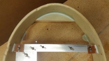
Here’s the front side of the headrest showing the glassed in place screw hard points.
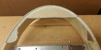
I then cut a very small trench in the foam around the perimeter of the front side of the top plate screw hard points and recessed inset. Before I then laid up 1 ply of BID just inside the recessed inset where the top plate will get mounted into, I filled the trench with thick micro. I then peel plied the layup(s).
Here’s a closer shot of the glassed front side top plate inset and screw mounting tabs.
I think I will have a few more hours on this GIB headrest before I finally get it glassed into place tomorrow, at which point I’ll transition into prep work on the nose and canopy builds.