
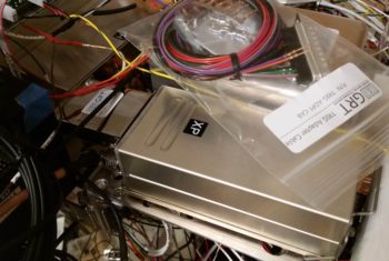
First off, before I begin my tales of wonder on the canopy and nose builds, I figured I would finally get around to showing you this…. over on the left side the pic, attached the front of the box that is the Trig TT22 Mode S Transponder is the GRT serial adapter which allows the GRT HXr EFIS control the remotely mounted transponder.
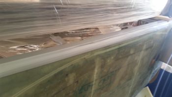
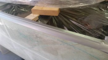
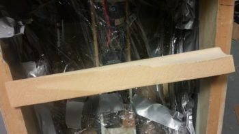
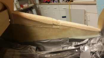
In the shop, I started back on getting the longerons prepped for the canopy frame build. On the left side I started by inserting a 1/8″ aluminum thick spacer atop the longeron, the length of what will be the entire canopy frame. As a reminder, this will allow me to do 2 things: 1) Place a 1/16″ hardpoint both front & aft on the longeron, then also a matching 1/16″ thick hardpoint both front & aft on the canopy frame, which will serve to maintain a 1/8″ gap between canopy frame and longeron. 2) Inside the constant 1/8″ gap I will lay in a “Double-D” seal that is 0.2″ thick. Proper compression is around 30%, so compressing it down to 1/8″ should allow for a proper seal of the canopy without crushing or mangling the seal over the years.
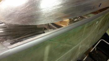
Based on my buddy Dave Berenholtz’ report during his canopy build that the 0.048″ thick glass on the BOTTOM of the canopy frame rails is not accounted for in the plans, with the builder being left to fend for himself, I used extra thick Gorilla duct tape for both tape runs here (above and below the spacer) to help account for that glass thickness.
I originally wasn’t going to put any spacer on the right side since it gets hinges… right? Well, as I was pondering the new mondo massive hinges I was putting in place I realized I had to account for the added height of these new, much larger hinges. They do in fact measure roughly twice the thickness as the original plans hinges (a bit over 1/4″ vs a bit over 1/8″). Since my canopy frame will not have as much surface area as the plans version, and will have narrower frame side rails, my revised plan is to simply leave the hinge depression on the bottom of the right canopy frame rail the same depth as per plans (0.150″).
The stock plans depression pretty much swallows up the entire closed stock hinge (both halves) whereas on my version it will only eat up half the hinge, with the other half exposed. Since half of my new, larger hinge is roughly 1/8″ thick, I decided to then also add a 1/8″ longeron spacer and configure everything on the right side canopy frame to be better optimized for using the seal over on that side as well. I will most likely incorporate the front and aft hard points as well.
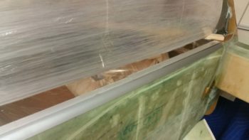
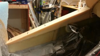
The only issue with my modified plan was that I only picked up enough 1/8″ thick aluminum stock to add a spacer to the left longeron. While I did have a considerable amount left over to use on the right side, I ended up having to rip a piece of scrap wood down to 1/8″ thick x 1″ wide for the aft end of the longeron (remember, from my pilot’s seat aft my longerons are 0.3-0.4″ wider than stock … 1.1″ total width).
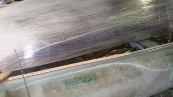
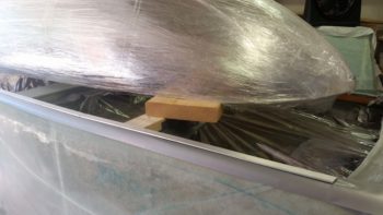
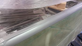
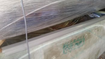
As I did on the left, I then taped the spacer in place with extra thick Gorilla duct tape.
I then left the canopy alone until after I get the nose glassed. Since the front height of the canopy frame will take its queue from the glare shield/drip guard since they intersect, I will pretty much finish the major glassing on the nose and avionics top deck cover before I finish the canopy. Yes, I was originally thinking I would do all at the same time, but I really have to do it sequentially now since the intersection of the front canopy frame and aft side of the nose cover is a bit intricate.
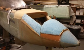
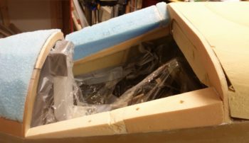
My first task was to get the area between F28 and F22 –where the canard sits– filled in with urethane foam that will act as a plug merely to be shaped, taped up and then glassed over to make up the aft nose/avionics top deck cover. I measured the first piece and cut it out of the big pieces of urethane foam I bought at the very beginning of the project not knowing that I would never use it on the actual aircraft.
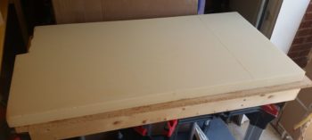
I then set it in place and secured it with a couple long sheetrock screws.
And then continued to fill in the gaping hole atop my nose section.
And finally got the canard mounting area hole, between F28 and F22, filled in.
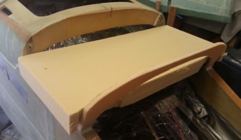
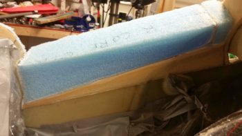
As you can see, I also found a perfect candidate block of big blue foam to fill in the front top part of the battery compartment, which sits immediately forward of the Napster bulkhead.
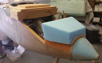
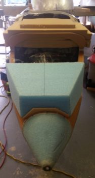
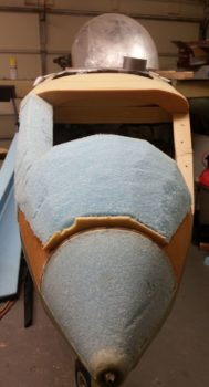
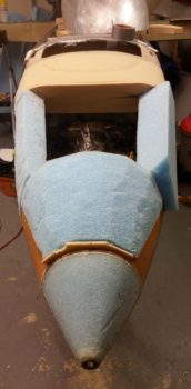
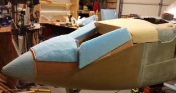
Here’s a front view of 2 of the 3 nose sections filled in with foam…. obviously needing some shaping to be sure.
I then hit a decision point. Which at the time I didn’t specifically identify as a decision point, it just happened rather organically. I had a related twofold issue at hand, the latter associated with my overall nose issue, which I’ll address shortly.
The first issue with adding foam to the area between the Napster bulkhead and the intermediate bulkhead was actually rather self-induced, in that simply the angles on each end are acute (less than 90°) and so I simply couldn’t just drop a block of foam in from the top. I did realize that this would be an issue when I glassed in the intermediate bulkhead, but I still felt the positioning of the intermediate bulkhead and its configuration was the best option when I did it… and still do.
My solution was rather a simple one, fill in the corner between the intermediate bulkhead and the existing nose sidewall so that the angle on aft end of the last open (non-foamed) nose compartment was more than 90° (obtuse angle to be specific). Not that hard, so that was the plan.
However, as I collected up my leftover scraps of 2″ thick PVC foam from the original nose construction, I was thinking A) how best to utilize these scraps (underlying tenet here: I’m cheap!) and, B) how do I best configure the foam to ensure clearance for the pitch trim actuator bracket.
Ok, stay with me…. haha!
All this pondering led me back to the original overarching issue that I have with glassing the nose, which is part 2 of my twofold issue from above: constructing the nose hatch. You see, my Davenport nose design does not lend itself well to having just one nose hatch, but two. Why? Well, it’s all due to that devious little basterd, Napster! Having a bulkhead right in the middle of your hatch makes constructing one (at least for me) a bit problematic.
I say this because normally hatches in the nose (on Long-EZ’s anyway) are made by simply filling in the nose with foam, shaping the foam, glassing the resulting nose shape, marking up the hatch on the new glass, then cutting it all off! Then with the removed nose shaped block of foam you whittle away the inside foam till it looks like a contoured nose inside…. then cut out the hatch, glass the lip in place and the rest of the interior nose foam, and then using the new nose hatch hole glass the nose structure back on with BID tapes on the inside between existing nose and new interior nose structure. Ah, not too difficult, eh? Until a bulkhead is placed in the middle of all that!
So, to end the bleeding on this segment of my blog, I will just state that I resorted to my normal course of action regarding airplane building at this juncture: I decided to simply build from the inside out. It will most likely add a day or two to my nose build, but I will get what I have identified as my requirement: a single larger nose hatch.
Thus, instead of changing the angles between the intermediate bulkhead and Napster, I simply started building the sidewalls. My idea is to finish the INTERIOR nose just up the point surrounding the hatch, and then carefully work it in conjunction with the battery compartment side of the hatch.
I then shaped a long wedge piece of PVC foam to add onto the right nose wall.
And micro’d it in place, securing it with nails (and one screw).
Not having one solid matching piece to do the same on the left side, I cobbled some pieces of 2″ thick PVC foam together to then make close to the same structure as on the right. I then micro’d these pieces in place.
With the multitude of angles at play on these nose pieces, trying to fit one in place is both maddening and time consuming. One has to simply accept the fact that rarely will you get a solid block in there at one go, and at least one other piece will have to be added… either at the front or back. And often two pieces will be required: one front and one back. I was able to get a decent sized chunk of blue foam in place on the right side with ONLY one required added piece to fill in the gap on the back side.
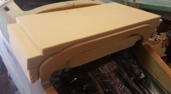
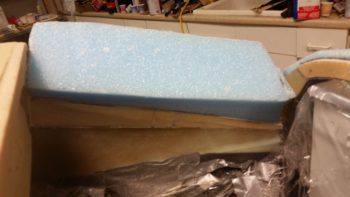
I thought I had taken a previous shot of this foam piece before I rough shaped the nose foam bits, but apparently not.
Another shot of the foam on the nose, roughly shaped. The foam piece I added in the middle section on the right (left in pic) looks thick, but a good majority of that will be sanded away when I do the final nose contouring.
To alleviate some of the problem that I detailed above in creating one large nose hatch vs multiple hatches with a bulkhead in the middle, is exactly why Napster came into being in the first place. When I constructed the nose pieces back in 2013, I determined the width of my hatch and notched the top of the Napster bulkhead (I don’t even remember the actual nomenclature of this bulkhead!) to allow for the thickness of the hatch door.
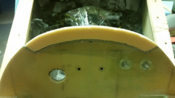
Here I’ve created what is going to be a transition point from the forward battery compartment to the NG30 compartment using a piece of 3/8″ thick PVC foam. It’s Napster’s toupee if you will, and it will serve essentially as an embedded bulkhead in the structure of the nose hatch door. Before I cut this foam out, I taped up the indention on the top of the Bulkhead (Napster’s head) with 3 plies of thick Gorilla duct tape to build in clearance between the nose hatch door and the Napster bulkhead. This duct tape will also serve as a release agent when it comes time to remove the hatch door (remember, I won’t be pulling the entire nose structure off like is traditionally done in building nose hatches since I’m scratch building the nose hatch in situ.
In line with what I said above, here you can see that the interior edge of the foam that I’ve micro’d in thus far is contoured close to its final shape as it will be to make up the interior nose wall. After one more piece is added to the right side, I’ll do a final shaping of the interior foam and actually glass it with a ply of BID.
Here’s a closer shot. At this point the walls are 1″ thick, and they’ll most likely narrow to about 0.8″ thick towards the nose top.
My final push for the evening was to mirror the right side and get a decent sized chunk of blue foam micro’d in place on the left side of the nose. It turned out fairly well, although due to the angles when it was finally micro’d in place I realized that for all surfaces to be as close as possible in maximum strength and to minimize micro usage, that the thickness of the wall is about 1.35″ thick… so more sanding down of the interior wall will be required before final glassing (it would have anyway, but this will be a bit more aggressive sanding to start).
It was late so I didn’t trim down the exterior of the newly added piece of foam… even more so because the micro hadn’t cured yet. So after almost an hour of cleaning up the massive amounts of foam and dust in the shop, I called it a night.
Here’s a parting shot for the evening of the nose under construction. It will be fun to look back at the nose in its current hodge-podge state, all cobbled together, to what it will eventually end up looking like!
Again, tomorrow will be all nose focused until I get it knocked out, then I’ll transition into the canopy build.
Lots of fun to see it happening so quickly. Love the round shape of the nose you have there. Much nicer than the plans fat and flat dugong look.
Thx my friend. Yes, nice to be getting these major steps on the nose knocked out. I look forward to seeing a glassed/working nose on there fairly soon! ;) Cheers.