I started out today submitting an order to ACS primarily for some more aircraft oil to replace the oil I lost out of the engine during the Great Oil Spill Disaster of May 2018. Since I was submitting an order anyway, I took a good half our to review my wheel pants 1/4-turn fastener requirements and added some more CAMLOC/SkyBolt fastening components to my order. I should just need one more final order on my wheel pants fasteners after this order when I do the first real install of the hardware and figure out my final requirements.
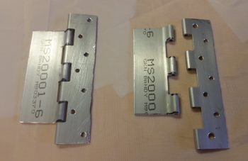
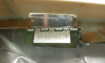
I then got into the shop and started off by narrowing the fuselage-side mounted lower hinge lock assemblies for the avionics top deck cover. After narrowing them, I drilled thru-holes for the flox to grip the hinge plates better.
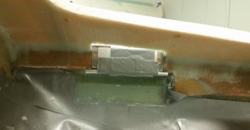
I installed the hinge pin (for the right side I used finishing nails) and then taped up both the inside and outside corner, with the upper hinge lock assembly in the vertical position… 90° to the hinge locking plate that was getting floxed into place.
I then floxed in the lower hinge locking plate on each side. After each plate was set in place with flox, I then made up a 4-ply BID prepregged layup for each side measuring 1.4″ x 4″ to secure the lower plate in place on the underside and overlapping onto the fuselage sidewall. Before laying up the glass I added a flox fillet in corner at the intersection of the underside hinge plate and the fuselage sidewall. I then peel plied the bottom edge with a 1″ strip of peel ply.
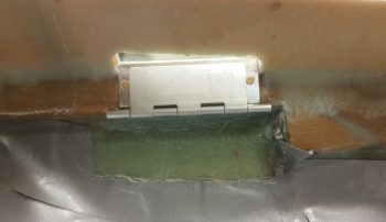
A few hours later I pulled the peel ply and removed the upper hinge lock assembly. Kind of a funny oops was that on the left side I can’t get the hinge pin out since there’s no clearance! No worries since I’ll need to drill a hinge pin hole through the instrument panel anyway. I would like to point out that the hinge pin is at the exact spot I was planning for it to exit through the panel.
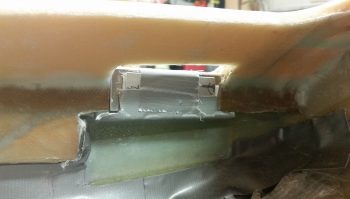
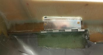
Here’s the upper hinge lock assembly back in place, in a down position to be able to see it better. To be clear, no “hinge” swivel action will be taking place with these hinges, they are simply locking devices to keep the avionics top deck cover secured in place.
This is actually a better representation of the upper hinge lock assembly since it will be pointed upwards in final configuration. Once the cover is completed and in place, this hinge lock assembly will be riveted to a tab hanging down from the underside of the cover.
I then spent another good half hour assessing and pondering exactly what methodology I was going to use to create the top cover. Throughout the past number of years as I have planned to have this aft nose/avionics top deck cover, I have considered the standard adding-then-shaping-foam method. Of course that called into question on exactly what type of foam to use? Blue, urethane, or pour foam? Or even a thin layer of PVC foam?
I also considered a straight glassing method, but then while it is simpler, it doesn’t allow for contour shaping which is something that really needs to happen.
Then, as I was moving stuff around in the shop this past week, I ran across some 1/16″ thick x 4″ wide strips of Balsa wood . . . hmmm? Could I? . . . interesting. Well, after playing around with the strips of Balsa wood, mystery #2 was revealed in just how to get the aft nose cover constructed: Balsa wood! Yep, with the avionics top deck sub-structure already at the proper angle, and my having sanded both sides to match in elevation, the Balsa wood strips will easily hold their shape spanning the avionics access hole and be flexible enough to contour to the surface of the avionics top deck. That will give me about 80% of the cover’s surface with just the area on each side forward of F28 up to the intermediate nose bulkhead to contend with… which I’ll simple shape foam in the more traditional method at these points.
With plan in hand, I worked it through a number of times in my noggin until I flushed out the various kinks and got a good handle on the sequencing.
As a point of note, the aft nose/avionics top deck cover really isn’t a huge cover and is just a bit over 2′ long from front to back. And about 2′ wide of course from side-to-side. The cover will have a minimum of 10 attachment points, but most likely 12 when completed.
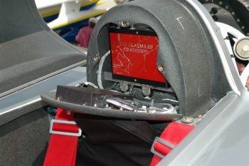
The last mystery to be revealed (#3) was the GIB headrest construction. I had pondered about this one too off and on over the years since I knew I wanted my GIB area to be patterned after Wayne Blackler’s GIB headrest. No offense meant towards any Long-EZs out there, but the plan’s method of creating a cavernous amphitheater-looking structure back there was not something I liked in the least. Yes, Wayne’s version adds a bit more foam and glass, but I much prefer the look of Wayne’s GIB headrest/aft canopy structure vs stock plans.
I will say that my GIB headrest structure will be just a tad smaller than Wayne’s by about an inch around the sides.
Again, I pondered, dreamed and aspired to reach the . . . oops, different story! Ha!
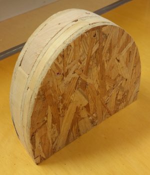
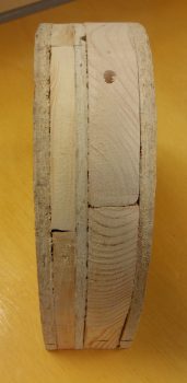
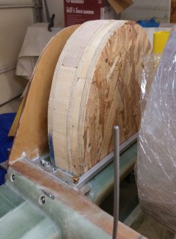
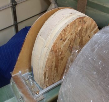
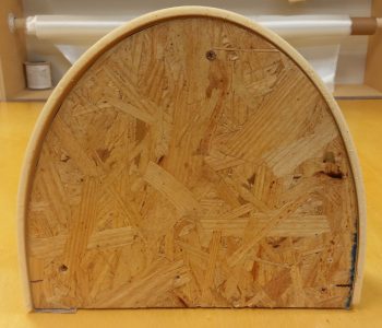
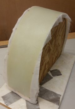
Yep, I wondered how the heck I was going to glass this structure while keeping its shape. Well, after spending a good 45 minutes finalizing how all the internals will fit, and using a very minutely modified version of the template that I created back in 2012, I simply cut out layers of scrap wood to create a form (or plug) for the foam.
Since we’re not talking about a hugely robust nor super high strength structure here, and since space was fairly critical –not to mention in short supply!– I went with 1/4″ thick PVC foam for my GIB headrest structure. Moreover, the 1/4″ foam would easily wrap around the wood plug without cracking… and without any required cajoling (read: heat gun!).
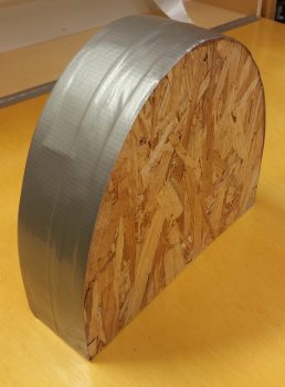
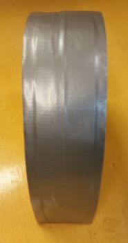
Just for fun, and to punk some GIB applicants [Final approval still pending . . . ] with my clearly comfortable headrest design <grin>, I did a quick mockup of the headrest plug. If you’re wondering why the plug is taller than the firewall it’s because I added heigh to it to make the sides a bit longer to allow me to secure the foam at the bottom of the plug with screws.
I then taped up the plug to protect it, but even more so just to level out the surface a bit.
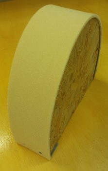
I then cut the 1/4″ foam and secured it to the form/plug with a couple of screws at the bottom on each side.
This front shot looks like the bottom edges distinctly curve in, but that’s a bit of an optical illusion since the camera is at a downward looking angle. Kind of a neat effect since the bottom edges are actually fairly straight!
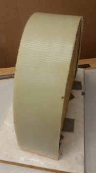
I then cut out and laid up 2 plies of BID on the GIB headrest foam. Boy, I’ll tell you, as an avid prepregger this free glassing stuff is for the birds! What a PITA! I thought I’d go ‘ol skool and just slap a couple of plies of glass on there . . . man is it high maintenance and finicky without that plastic keeping it all wrangled and in place.
Lesson learned!
I then peel plied it of course. I took the pic above because I really do like the look of the non-peel plied weave in fiberglass, but when it comes to adding more plies, finishing and painting, it’s a pain to have to sand it to get the glossy cured finish knocked down… especially inside the weaves.
Tomorrow I’ll continue to work my headrest and start the prep for the aft nose cover, forward nose foam structure, and canopy install.

