
Today I started out by pulling the peel ply off the Oil “tower” box and then cleaning up the surface of the box.
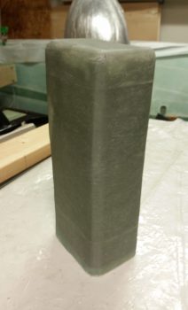
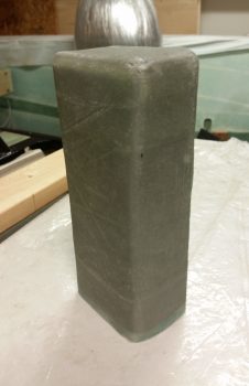
I then took the box out back and gave it a work over first with the hard sanding block to knock down the high spots, then with a piece of 32 grit sandpaper over the entire surface. I then washed off the dust and set it out in the sun to dry.
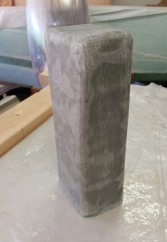
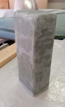
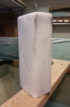
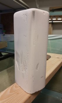
After a visit from my neighbor and my ensuing build update, I then “frosted” the oil ‘tower’ box with micro icing.
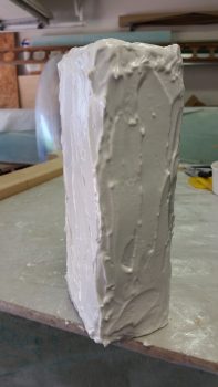

A couple of hours later, after I had assessed and prepped for the foot vent ducts, the micro had cured to just past the green state so I hit it with a hand grate and then the 32 grit hard block to “cheese grate” the surface…. essentially knocking down all the ridges while the micro is still slightly pliable vs rock hard. I then left it to cure and will do the final sanding tomorrow.
I then finished determining the configuration & spacing of the front left duct that makes up the left foot vent. At the aft end is an inverted “T” junction that allows heating air to pass upwards to the instrument panel eyeball vent. I’ll test the system out when I get the plane flying and if required I’ll add a butterfly valve to the “T” junction to control the airflow. Also, I may end up tweaking the very forward tip of the duct, which currently just opens up to make up the foot vent.
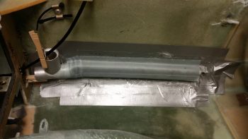
After narrowing the strip of urethane foam –that I’m using as the duct plug– from 2″ wide down to 1.5″ (still 3/4″ thick), I then taped up the lower sidewall in the avionics bay area. I then radiused the corner edges of the foam plug and taped it up to the wall over the existing protective tape. I of course had to do some foam machinations for the “T” junction to duct transition, and got it after a bit of finagling.
I then used a lot of small pieces out of my scrap glass pile to glass the first layer on left foot vent duct, with final bigger pieces of UNI to tie the smaller pieces together. I used fast hardener on this side and after laying up the glass I then peel plied the layup.
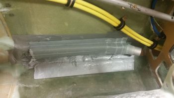
I then prepped the right foot vent duct in much the same manner as the left side. I originally had the aft duct connect tube pointed more inboard at a 45° angle, but then wanted a lower sidewall profile. The angle of the aft duct connect tube actually allows me to run scat tubing through either of the lower panel openings, providing more routing options if I should need them later on.
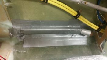
Then, just as the left side, I dug into my scrap pile and used a lot of the smaller pieces for the first ply, then covered those pieces with larger UNI pieces to make up the second and final ply on top. I used slow hardener on this layup since I knew it was going to cure overnight anyway. I then peel plied the layup,
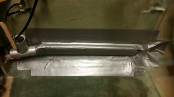
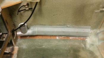
After laying up the right side foot vent duct I then pulled the left side foot vent duct off the sidewall, tape, plug and all. Then, after removing the foam plug and tape from the actual duct, I then set it back in place for the pic below. I will need to add a small amount of glass around the aluminum tubes that are embedded into the ducts on each side to finalize sealing up the ducts, but after that a trim of the glass down the sides then these foot ducts will be ready for install.
Tomorrow I’ll finish sanding the oil “tower” box and then epoxy skim coat it in prep for paint. I’ll also finish the foot ducts as well. Then I’ll mount the canard to allow me to glass in an elevator up (nose down) hard stop on the fuselage sidewall. This will fulfill the safety requirement outlined by Trio Avionics for the installation of their autopilot servos (i.e. don’t use the autopilot as a hardtop of the control surfaces . . . could damage the pitch servo).
In addition, I will finish buffing out the NG30 cover and install it, then finalize the installation of the Radenna SkyRadar ADS-B on top of the NG30 cover. Also, I’ll re-install the pitch trim servo to assess interior nose clearances. Finally, I plan on mounting the 4130 tubes and nutplates in/on my modified longeron doublers near F28 in order to use long AN3 bolts to attach/secure the canard lift tabs to the fuselage.