
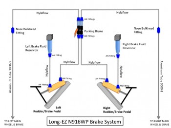
Today I started off by doing some research as I watched some football. The first thing I had on my list to figure out was the exact configuration of my brake line components. I did some poking around on the Matco website to figure out what components go where for my brake system. I found the information I was looking for and was able to tailor it to the brake system components I have on hand.
Again, being a true Neanderthal and PowerPoint Ranger, I jimmied up a quick PowerPoint slide to display what was going on with the brake system. One reason I was checking out my brake system is because I wanted to confirm what goes where in the nose so I can plan better as I build the NG30 aft cover, and will soon glass in the nose side walls.
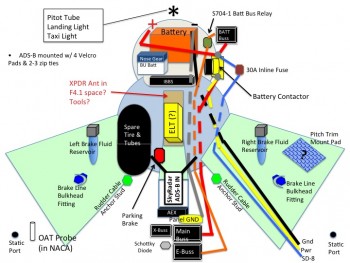
I also spent about an hour doing some digging around online for information on my electrical system. Really, I was focusing on a lot of the little bits n’ pieces that will be required to finalize the mounting of various stuff in the nose area, such as Adel clamps, and hardware to mount those Adel clamps: screws, nuts, bolts, washers, etc.
I also ordered two different sizes of heat shrink tubing for my shrink wrap label maker. Now I have at least the first round of wire labeling for my wires ranging from 4AWG to 22 AWG.
I also updated my nose component diagram again and included it here.
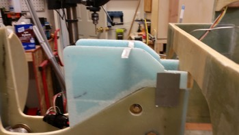
I then headed out to the shop to razor cut the edges of the NG30 cover side panels. Here’s the left one after I mocked it up on the NG30.
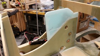
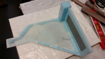
And here’s both trimmed side panels mocked up.
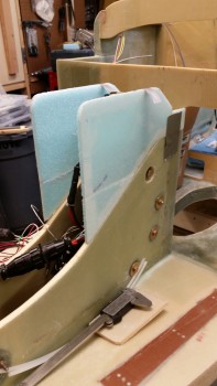
A side view of the NG30 cover side panels.
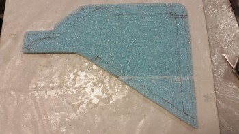
I then spent a few minutes figuring out what foam was going to get cut away & which foam would stay. Here’s the marked up left NG30 cover side showing the foam cut lines.
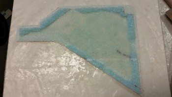
Here’s the final foam trim for the left NG30 aft cover side panel. Out of curiosity I weighed this side panel and it came in well under 1 oz.
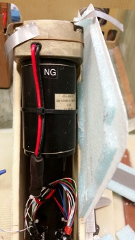
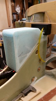
I then double-checked the actuator motor housing clearance with it back on top of the left NG30.
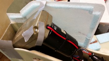
Here’s a front view of the same.
I then cut out the 1/4″ front foam panel and the front top corner foam piece. Below is a shot of the pieces mocked up to ensure that they fit.
I then attached these foam pieces to the left side panel using 5-min glue.
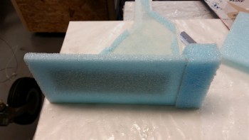
Piece by piece, I cut and then glued the top and aft blue foam panels into place on the left NG30 side panel. I really focused on ensuring that these glued-in panels were truly perpendicular to the side panel. Note that I intentionally cut the top front corner piece oversized to allow for sanding it down to a curve that’s “pleasing in shape” …. ha!
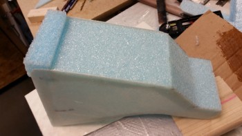
Here’s a shot of the NG30 aft cover after I glued in all the center foam panels & pieces.
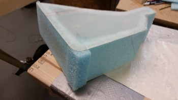
And an aft side view.
After sanding the foam & glass edges to shape, I mocked up the cover on the NG30 nose gear box.
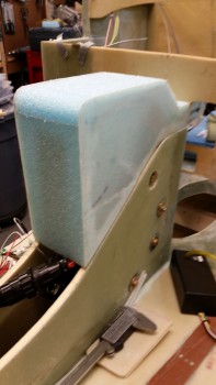
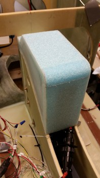
I grabbed the AEX box and put it in its spot to check how it fits. Spacing looks good!
As I took a break for dinner, I was thinking about the front of the NG30 aft cover and had a mini epiphany. I wasn’t sold on the straight horizontal positioning of the nose gear’s P1 connector. I doubled-checked it when I got down to the shop and sure enough, the P1 connector would fair much better if it was positioned at an angle vs attached straight through the front panel. Although I knew it would be a bit more work, I wanted to optimize the nose gear actuator’s P1 Amp/CPC connector’s fit into the NG30 cover.
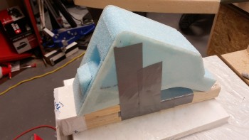
I drew out the plan on a piece of cardboard, then transferred that to another piece of cardboard to make a template out of it — which looked like nothing more than an “S” if you wrote it without any curves (a 3-lined zig-zag). I transposed the template markings to the side of the cover.
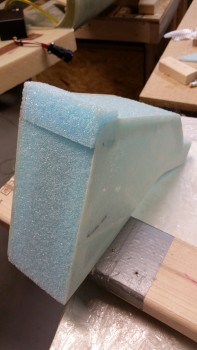
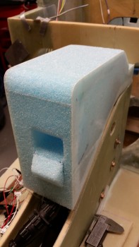
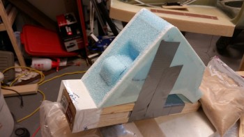
I needed to make what essentially would end up being a male mold (lower) and a female mold (upper) in the front face of the cover for the BID to end up curing in the correct shape. I made the front angled panel piece (lower/male) to match the profile of the template and markings on the side of the NG30 cover. With that piece completed, it was then time to figure out how make the angled pocket (upper/female) to finish off the angled mount for the P1 connector. I ended up adding an oversized chunk of foam on the back side of the front foam panel piece on the inside of the cover. I 5-min glued it in place at the same time I glued the front “ramp” (male) piece in place, and stood there holding the two in place for about 5 minutes (what a coincidence!) until the epoxy set up.
Now, I have been contemplating how exactly to go about glassing the NG30 aft cover. I wanted to get a good glass overlap, perhaps even an entire piece of BID over all of it, but the cured 5-min glue and the edges were being amazingly stubborn as I toyed with radiusing the corners. I will say that I really do like the look of the sharp square corners, but I don’t like the idea of digging around in the confined nose space and smacking my arm on that sharp corner. Oh, well, who cares how it functions as long as it looks awesome! haha!
I mounted the NG30 aft cover assembly onto a 2×4 to ensure that this incredibly light assembly didn’t get away from me as I was glassing it.
I then cut a small trench along the corner edges and cleaned them up in prep for Flocro.
I mixed up some epoxy with fast hardener and then whipped up some Flocro with about 60% Micro & 40% Flox. I used Flocro to keep it light but still have good strength in the corners. I applied the Flocro along the edges of the foam in the mini wedge-shaped trenches that I had just created to make my “Flocro Corners.”
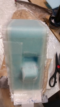
I then laid up 2-plies of BID on all but the very aft area of the center piece of the NG30 cover. I had meant to take the layup farther aft, but the connector mount area took up a bit more glass than I thought.
I peel plied the entire layup since I’ll probably add one more ply of BID to this center section area. I may even still radius the corners a bit and layup BID overlapping from the sides over onto the top & front center faces.
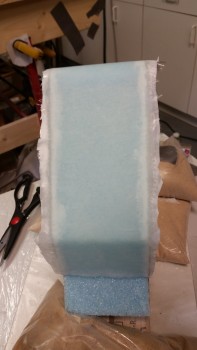
Here’s a shot of the aft side of the layup.
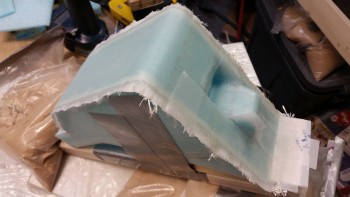
And another shot of the majority of the layup (there’s about a 1.5″ strip overlapping onto the angled panel that dives down into the notch for the AEX… shown in above pic).
Tomorrow I’ll work to finish up the myriad of little tasks that need to be completed to finish up this NG30 cover. I estimate that I’ll finish this cover either Tuesday or Wednesday.