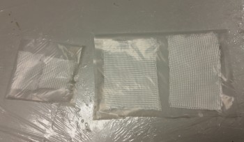
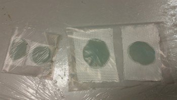
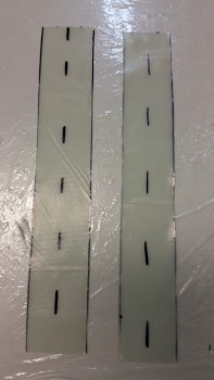
I started out today by setting up the prepreg BID for the lower half of the NG30 to F22 layup.
I mixed up some epoxy with fast hardener and wetted out the prepreg BID.
And then mixed up some flox and applied it to the corners.
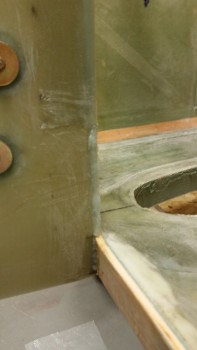
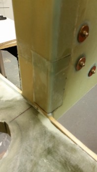
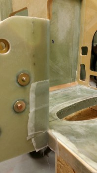
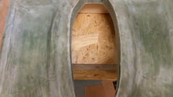
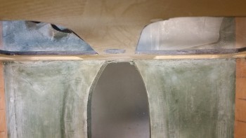
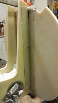
Below is a shot of the 2-ply BID prepreg layup for the right external NG30 to F22 attach. I overlapped the bottom layup over the first (top) layup by an inch.
I then peel plied the layups. Note that I also laid up 2 plies of BID in the very bottom corner between the NG30 plate and the F22 plate.
While the NG30 glass was curing I started working on mounting the fuselage further forward on the fuselage dolly so that there would be plenty of clearance for the front wheel ingress & egress from the nose gear wheel well.
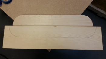
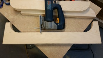
To move the fuselage forward I needed to cut another fuselage saddle wider than the current forward saddle. I marked up a piece of wood and cut it out.
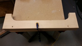
I then clamped the old saddle over the new undrilled saddle. I drilled through the existing holes to make the new mounting holes.
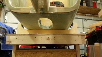
Here’s the new saddle in place and mounted with the 5/16″ bolts…
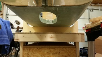
allowing me to move the fuselage farther forward on the dolly. I also added another tie down strap.
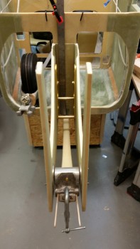
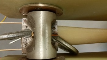
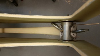
With the nose wheel clearance taken care of I started working on mounting the nose gear strut (NG1-L) to the nose gear pivot (NG6B). I mounted it temporarily using clamps, and spent a good 20 minutes getting it aligned down the center of the channel.
I also temporarily mounted the nose wheel to ensure their was enough clearance for the wheel in the wheel well. It was close, but there was just enough clearance aft of the wheel.
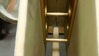
Once I got it aligned I loaded my drill with a 3/16″ bit and started to drill starter holes in each of the 4 holes in the NG6B.
I should probably offer a reminder at this point that I’m using Jack Wilelmson’s NG6B vs the NG6A (or the original NG6). The NG6B differs in that it uses two separate bolts to hold it in place –one from each side– rather than the single long bolt that the NG6A uses. This comes in rather handy if you want to remove the nose gear pivot after the nose is built. Unfortunately, the NG6A bolt can’t be removed easily after it’s installed since the bolt is too long.
The NG6B also comes with the 4 screw holes pre-drilled which makes it really nice when it comes to this part of the build!
My initial plan was to simply drill some starter holes since that would give me the exact locations of the screw holes. I would then finish drilling the holes on the drill press later. Well, as I was drilling the starter holes, it occurred to me that the bottom of the nose gear strut isn’t straight, level or even, so mounting this horizontally & level on the drill press table would not be an EZ endeavor. So, in the name of optimizing time and getting this done I went into Maverick mode and just finished drilling the holes with the power hand drill, freestyle.
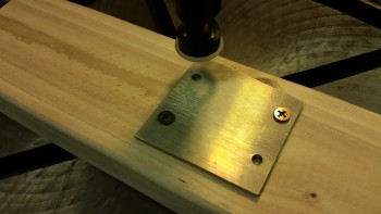
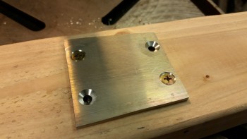
Now, I did use the drill press to drill the countersinks into the NG-5 plate. I screwed the NG-5 down to a 2×4 with 2 screws. I then drilled the first two countersinks, swapped the screws and drilled the last two countersinks.
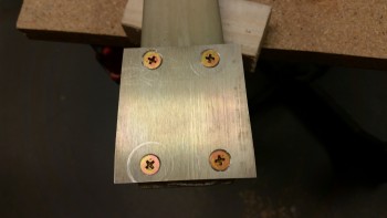
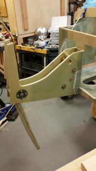
Here’s the finished NG-5 plate screwed in place to the nose gear strut. The ring around the lower left screw in the pic below is because by using the countersink drill bit assembly on the drill press obviously works differently than using it on a hand drill, where with the latter when you press down on the plate it stops the support plate on the drill bit. When using it on a drill press you have to manually stop the support plate from spinning before engaging the actual bit.
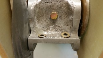
All NG6 assemblies seem to require that the areas around each screw hole be ground down to allow the washers & nuts to fit. Below you can see that I Dremeled out the area around the hole on the left, while the hole on the right was not yet completed.
The aft holes seemed to be ok for now, so I just added some temporary nuts and tightened everything up. It all lined up great.
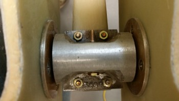
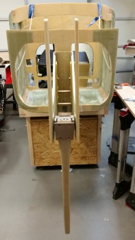
Here are a couple of shots of the nose gear strut in place.
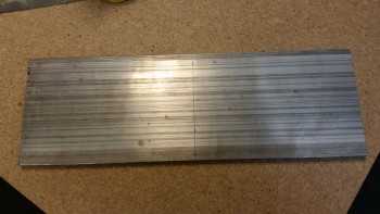
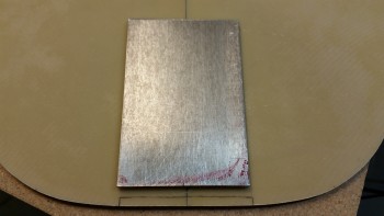
I then started working on the 1/4″ 2024 aluminum skid plate that I’ll be mounting on the lower nose. I marked a cut line at 6.2″ and then cut it at 45° along this line.
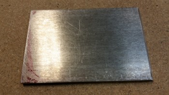
Here’s the raw cut skid plate.
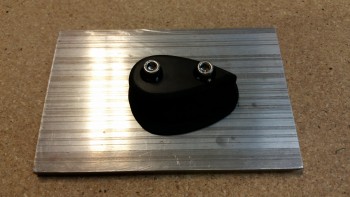
The skid plate will also serve as the mounting plate for the rubber nose bumper that my buddy Marco made for me.
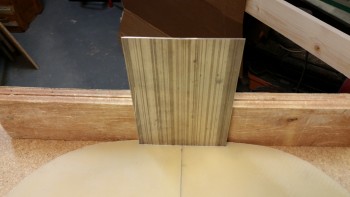
I cut out a notch on the bottom of the NG1-3 bulkhead, or “Napster” as I call it, for the skid plate… using the skid plate as the template.
I then tested the fit. Not bad.
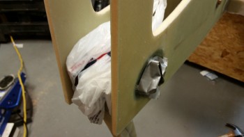
With Napster prepped, I then taped up the NG6B and its hardware in prep for installing Napster to the forward NG30 uprights.
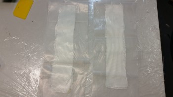
I started prepping the 2-ply BID tape prepreg setups for mounting Napster to the NG30s.
I mixed up some epoxy with fast hardener and then made up some flox. I then applied a bead of flox to front edge of each NG30 upright.
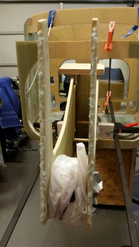
Then I cut the BID prepreg setups to size.
And then laid up the BID tapes on the outboard sides of the NG30 uprights.
After a good night’s cure I’ll remove the NG6B nose gear pivot and lay up the inboard BID tapes to finalize the Napster bulkhead install.
Tomorrow is Thanksgiving so the build will be light, although I will try to get the inboard BID tapes laid up.

