
A NG30 cover that is!
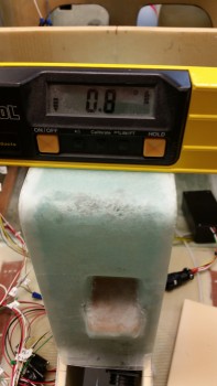
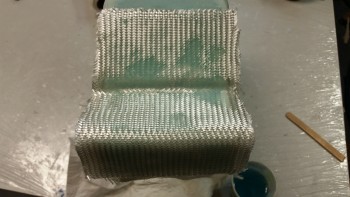
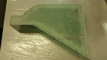
Today I started out by checking the angle of the longitudinal axis with my digital level across the longerons. I got a reading that said the right side (looking from nose to aft) needed to come up 0.2°. This also gave me my baseline for checking the NG30 cover.
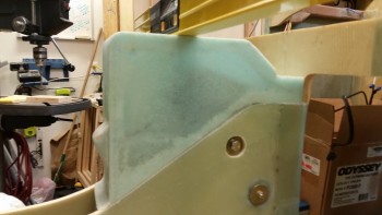
When I checked the NG30 aft cover it showed that it needed to come up 0.8° on the right side (again, looking nose to aft). When I pressed down on the back left corner (as oriented in the pic below) I was able to take the number down a notch to 0.7°.
Now, I wasn’t trying to be a perfectionist here, but I did want to get it as close as possible, primarily because I’m fairly certain I’ll be mounting the Radenna SkyRadar-DX ADS-B IN receiver on top of the NG30 aft cover. I want the top surface of the NG30 cover to match the longerons in longitudinal axis since the SkyRadar has a built in AHRS and needs to match the axes of this aircraft to provide attitudinal information. Getting the cover as close as possible to the longerons will just make things easier when installing the ADS-B receiver, and help ensure better info if ever a backup attitude reference is required.
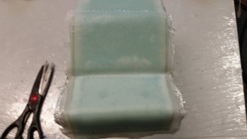
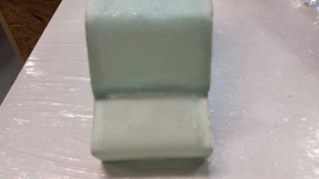
I slowly sanded down the edges on all sides at various points to get this cover dialed in. I did focus on the left side (again, relational to the pic below).
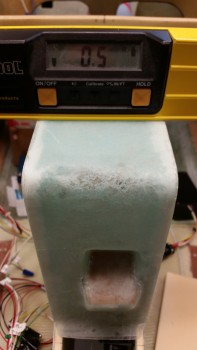
And after about a half hour, success! Add this time to the original half hour rough cut on the bottom edges after the sides were glassed and I spent about an hour total by this point on getting the cover level.
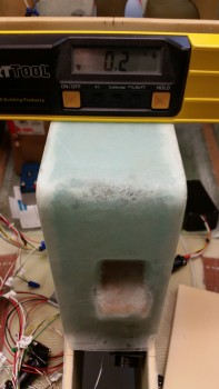
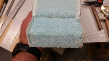
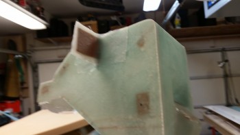
Here are a few shots of the level NG30 aft cover. There are still some minor gaps that will be taken care of during the finishing process.
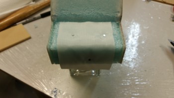
Now, I made an oops as I was ripping off the peel ply from the right side layup from last night. It was pretty tough at one point so I put some muscle into it, and apparently some of my fingers where on the back foam plate because it gave way and the foam snapped.
Not really an issue since I planned on removing this foam anyway. Luckily, the foam broke into 2 big pieces, so I merely taped them back into place with duct tape.
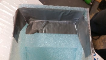
Here’s my repair. See?! Duct tape will fix anything!
Since I am removing most of the aft foam almost immediately after the glass cures, and then laying up the aft inside area of the cover, I went ahead and embedded some peel ply to ensure the main surface was prepped nicely for glass.
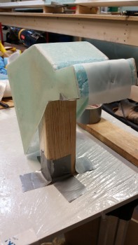
I then taped up a quick glassing tower for the layup (it was a bit wobbly if I really applied pressure since it was only taped to the protective plastic on my board, but this helped me keep my touch lighter on my improvised foam repair).
I cut out wedged-shaped trenches along the outer side edges and filled them with flocro.
I then laid up 3 pieces of BID in 2 plies. The first ply is from the corner seam aft, the second is from the corner seam forward, making up the first ply of the layup. The third piece of BID and second ply covers the entire area of the first two pieces of BID. I wasn’t sure how well the BID would lay down in the tight 90° corner, so I split the first ply into 2 pieces.
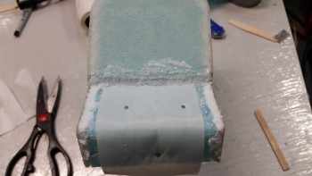
Here’s the final result of the aft end layup. I have to say I really wasn’t looking forward to this layup, but it turned out to be one of the better, more relaxing layups that I’ve done on this cover.
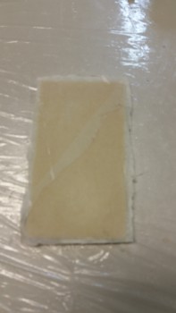
I also laid up 1 ply of BID on the backside of the second draft plate that I cut and glassed last night.
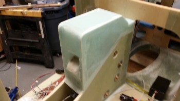
To mark where my nutplate assemblies will go on the right side of the cover, I grabbed my original template and punched holes with an awl everywhere it indicated a nutplate assembly mount.
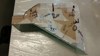
I then simply marked the right side surface with a Sharpie through the holes I had just made in the template with the awl.
Since 2 of the new nutplate assemblies going inside the cover will be very close and adjacent to the aft layup area, I went ahead and prepped that area first before floxing & glassing in the nutplates.
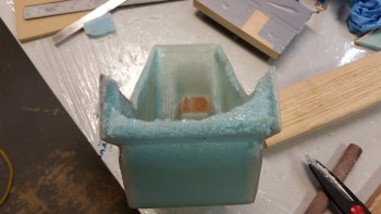
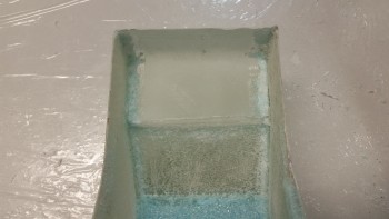
I dug a bunch of foam out and then pulled the peel ply from the inside of the aft area.
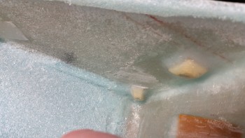
Here’s a better shot of the foam & embedded peel ply removed.
I then finalized the prep of the aft area internal glass for a 1-ply BID layup.
Since I was still helping my buddy Greg with his Christmas tie, I didn’t get a chance to take a pic of this layup until an hour or so later, If you look closely you’ll see that I installed 3 new nutplate assemblies on the right side panel, and embedded 2 pieces of phenolic on the aft pad where the AEX will get installed.
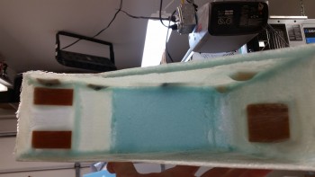
I then took a piece of phenolic that I had precut and mounted it the right side sandwiched between 2 x 2-ply BID prepregged BID tapes. This mounting tab will house the permanent P2 connector coming from the main P1 connector at the front of the cover. Then the AEX side P2 connector will plug into the mounted P2 connector.
I floxed and glassed two strips of 1/16″ phenolic in the back to serve as mounting hard points for the AEX box.
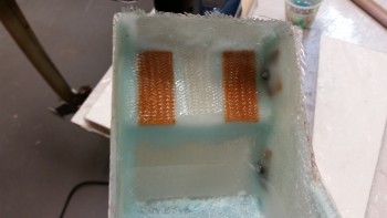
Here’s a shot of the nutplate assembly I glassed in last night (far corner) and the one I floxed & glassed in today (nearer camera)
I know I said I was going to be done with the NG30 cover today, but that was before my buddy Greg needed my help. I think I should have almost all, if not all, of it completed tomorrow.