
Today started off as an inventory day since both my Aircraft Spruce and SteinAir orders arrived. I spent well over an hour organizing & consolidating all the myriad of hardware, fittings and pieces parts.
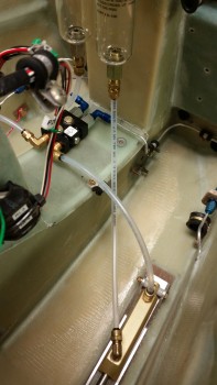
I was waiting for a couple of key pieces to arrive and installed them immediately after unpacking them to see how they fit. For example, below is a new 90° Nylaseal elbow fitting installed on the the aft end of the brake master cylinder. Also, I cut the Matco 1/4″ nylon brake line tubing with my new plastic tubing cutter from SteinAir… spiffy!
As you can see, the 90° Nylaseal fitting on the master cylinder works great, and the brake tubing flows easily from the brake reservoir to the master cylinder, which affirmed my decision to mount the reservoirs where I did. As for the left side, I still have to remove the rudder/brake pedal to remove the brake reservoir.
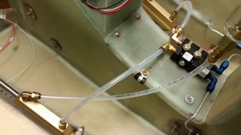
Here’s another shot of the right master cylinder to brake reservoir connection.
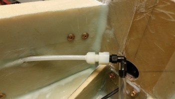
I also received a new Nylaseal fitting for the pitot system line. I cut off a short piece of the Nylaflow (gotta practice!) and then checked to see how the fittings for the Tygon worked. So far it all looks good.
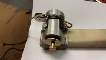
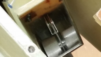
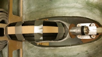
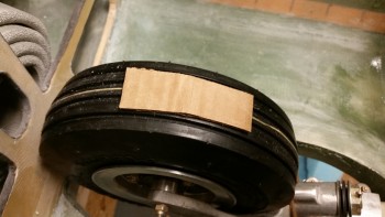
I then moved on to my in-house R&D project. Below you can see a band of very tough strap-LIKE metal (I’m fairly certain this stuff is stainless steel, because it is as hard as all get-out!). I spent a good number of minutes drilling out a hole towards the middle that will allow me to rivet a pulley (shown in the pic) to the metal strap.
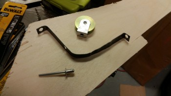
Once I riveted the pulley in place, I then grabbed my brand new piece of 1/16″ stainless steel cable (that I also got from ACS today) and swaged it into a stainless steel L-braket, which I spent over a half hour also modifying to accept the cable thimble.
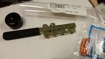
Here’s the swage tool that I used. Not bad.
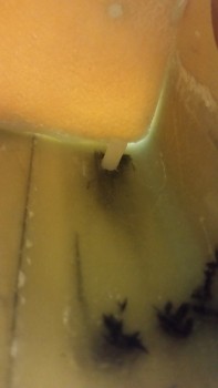
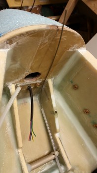
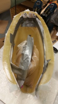
Here’s a quick shot I took as I was trimming the length of the Nylaflow taxi light cable conduit down underneath of the draft plate & on the aft side of Napster. There’s some daylight showing in the corner where the draft plate is mounted, but remember I still have to do all the bottom side layups for a bunch of stuff when I flip the bird over to glass the bottom of the nose.
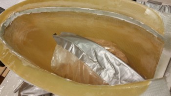
I hooked the nose gear strut up to the nose gear actuator and very slowly raised the gear, stopping every little bit to check with a mirror to make sure I wasn’t tearing anything up.
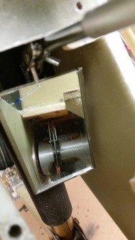
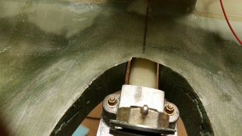
Here’s another shot with the mirror of the taxi light pulley actuation bracket.
And here’s a shot of the taxi light actuation cable.
I then slowly raised the gear & also stopped every so often to ensure that nothing awry was going on with my taxi light actuation cable bracket mounted on the NG6B.
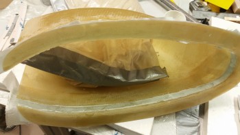
On a separate note, when the gear topped out in the nose wheel well it was exactly what I wanted to see: the gear strut center of mass in the gear strut channel . . .
… with the gear strut elevation looking good in comparison to what will be the bottom sides of the nose.
And the wheel tucked out of sight nice n’ neat!
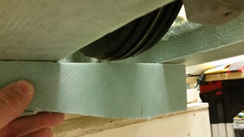
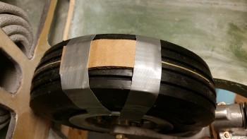
With the gear up/down good, I then turned my sights onto the nose gear wheel well cover (NB). I taped some 1/4″ foam to the top of the wheel to ensure clearance with the wheel well cover (NB).
As you can see below, there wasn’t more than a 1/4″ clearance with the wheel in the wheel well.
I taped a smaller 1/4″ thick piece of foam on the wheel to see how much of the wheel was affected by this clearance.
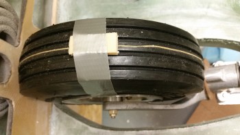
At this point on the aft side, if I moved the wheel any farther forward, then NB would start to pop up.
And the same here on the front side, where moving aft would cause NB to raise up.
So the arc of effect wasn’t huge as to be expected, maybe 45-60°? I then grabbed a piece of cardboard that measured just under 0.150″ thick. I was getting ready to try this pretty much as I had done above…
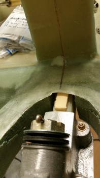
… when my eyes caught a glance at this (pic below) . . .
The top of the gear strut was almost a 1/2″ below the top of the gear strut channel (aka “the fuselage floor”). I had seriously contemplated being lazy (or, efficient!) and go with the 1/8″ clearance and simply install the NB, which would still allow the wheel to be free & clear in the wheel well. But then if I ever needed to adjust the gear strut to close more fully it could easily do some crunching! Also, if the microswitch were to slip in its mount it could do some damage if I didn’t have more wiggle room built into the configuration.
My original estimate was that I’d add about 3/8″ to the NB, and that’s about right since in calculating my gear strut channel spacing I could fold the cardboard in half and slide it in over top of the 1/4″ thick foam, barely. So I tried the test below…
I simply put the cardboard on the wheel without any tape holding it in place. Then I rotated the wheel freely front & aft, which told me there is at least 0.150″ clearance between the wheel and the wheel well cover (NB).
This makes 3/8″ a good number to increase the height of NB. In the nose gear strut channel, I measured a space of 0.25″ + 0.15″ + 0.15″ (the folded cardboard) which when measured all together comes out to 0.55″. Now, take away a bare minimum of 0.15″ clearance that exists in the wheel well between the tire and NB, and that leaves 0.4″. If I increase the height of NB by 3/8″ (0.375″) then the remaining is a negligible 0.025″ …. which could easily be swallowed up in the real clearance space between tire & NB, and I’m fine with that call.
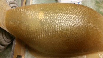
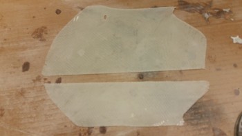
The first order of business concerning the NB was to sand it.
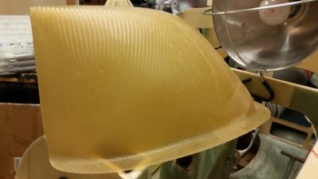
I sanded the sides & flange, both top & bottom starting off first with the hardboard & 36 grit paper, and then used the orbital sander with 36 grit paper attached.
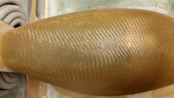
Here’s the left side sanded.
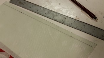
And here’s the left side with the cut line marked just above the mounting flange.
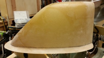
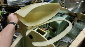
I then used the Fein saw to cut the NB into two different pieces.
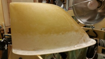
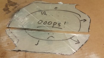
Remember that Ooops! glass from when I had way too much while I was glassing the NG30 inboards aft edges? Well, here it is! You can see in the progressive pics that I pulled the plastic from both sides and then sanded the 2-ply BID pieces with the orbital sander.
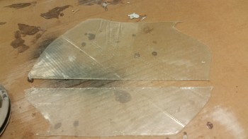
I then cut 4 x 3/8″ strips from the Ooops glass.
And embedded those 3/8″ strips into the side of the NB cover. On the inboard side of the junction between the Ooops glass strips and the upper & lower NB pieces, I have a strip of 1″ peel ply, then tounge depressors (stirring sticks) wrapped in packing tape. Finally, this is all held in place by a strip of duct tape.
To start off on the left hand side, I actually 5 min glued some of the critical junctions to get the somewhat unruly Ooops glass strips to stay put.
I then used a thick layer of flocro over the seams, and laid up 2 prepregged plies of BID.
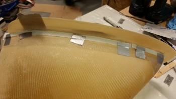
After getting the left side all laid up & peel plied, I set it under the heat lamp while I prepped for the right side layup. The weakest areas that wanted to pull away from the shape were the 2 front lower corners, so I jimmied up some clamps using clothespins to hold them in place.
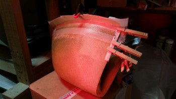
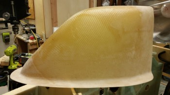
This is what it looked like nearly 2 hours later. You can see the interior tape setup holding the 3/8″ Ooops glass strips in place.
And here’s what I found after I removed the tape & peel ply.
I spent a few minutes cleaning up the still green flocro. I’ll wait until it gets a good night’s cure and sand it tomorrow.
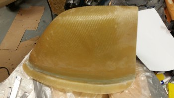
Finally, here’s a shot of the taller NB nose wheel cover. Again, I’ll clean it up more when it’s full cured tomorrow.
Tomorrow I plan to install the NB, remove any fragile or excess items from the interior nose, flip the fuselage, sand the nose and at least get it all prepped for glassing, if not tomorrow night, then on Saturday. In addition, I still need to prep & install the gear strut cover before the lower nose gets glassed.