
Today I started off by cleaning up the left side panel by first pulling the peel ply, then razor trimming and sanding it.
I then did the same thing with the right side panel. I also drilled out the bolt holes.
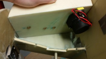
I then test mounted the battery contactor.
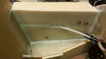
And then test fitted the right side wall with the contactor mounted in place.
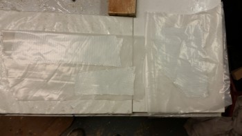
I then made up some prepreg setups for the BID tapes to mount the right side panel.
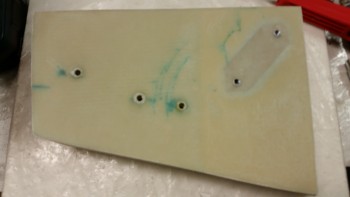
I realized when I was uploading these pics that I missed taking a pic of the right side wall after the layup. So after the right side panel cured, I pulled the peel ply and cleaned up all the peel ply boogers. I razor trimmed it as per usual, and then sanded the edges.
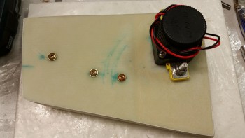
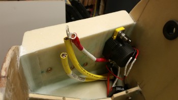
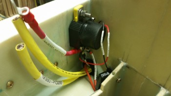
I drilled out the holes in the contactor mounting plate and then mounted the contactor. Before mounting the contactor I terminated & labeled the 30 Amp inline fuse wire and the control leads on the contactor.
In addition, I attached every wire & cable to the lower terminal that will actually be mounted in the final configuration to ensure that all the wire runs are good. The only thing I could improve upon here is to cut the lead wire form the 30A inline fuse down an inch or two.
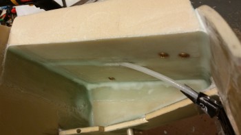
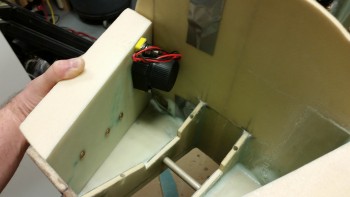
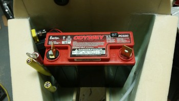
I then checked the fit of the battery with the contactor bolted into place. I was very pleased with the clearance between battery & contactor since it was even about 0.070″ more than I thought it would be.
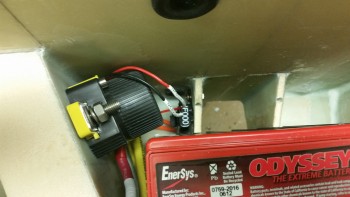
The space on the right side of the battery is a bit tight due to the 3 big cables all trying to get through that narrow space: the 2 big power cables going to/from the firewall and the main power lead from the battery to the battery contactor. It’s definitely crowded, but not unworkable or impossible.
Here’s a shot of the cable & wire runs to/from the battery contactor.
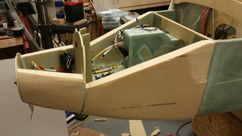
After I got the right side panel of the battery compartment squared away, I started prepping the F-7.75 bulkhead for mounting the nose tip foam to finalize the shape of the nose. While I was trying to assess the front tip of the nose, I felt I just needed a better visual of the “flow” of the nose. I picked up a saw and started hacking away. I then used my hard sanding board and my “cheese grater”.
About 30 minutes later I had this. Satisfied, I stopped for the time being and pressed forward with the nose tip.
The nose tip is 6″ deep, so I had originally planned to use 3 pieces of 2″ thick foam stacked in wedding cake fashion. My thought was that the aft 2 pieces of foam would be the blue large cell (wing) foam with a PVC foam front tip.
When I tried to locate a suitable sized PVC foam for the very front tip, I couldn’t. The only way I could fulfill my plan was to glue 2 pieces of PVC foam together. So I decided to go with all blue foam. I’m using the blue foam for a couple different reasons besides not having enough PVC. First, I have a TON of it on hand since it encased all the wing foam cores and other flying surface I received from Feather Light. Second, I had originally planned on building the entire nose with the blue foam to cut down on weight. Since the original nose identified in the Long-EZ plans called for Urethane, and the foams are the same strength (2 lb/cu ft), I was going in that direction until I ran across the Davenport nose plans, which calls for the PVC/Divinycell foam which is stronger at 3 lb/cu ft.
I still plan on using the blue foam on the top portion of the nose.
I grabbed a nice piece of 2″ thick blue wing foam to use as the first (aft) piece that will physically mount to F-7.75. I then marked the center of the foam piece.
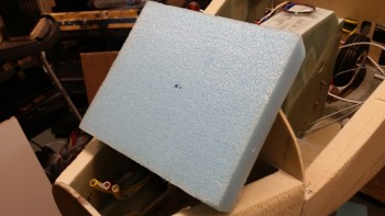
I then roughly marked the outline of the F-7.75 bulkhead. and cut the foam on the online (not shown).
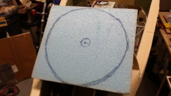
I was hunting around for better pieces of foam to use in front of the piece above, analogous to the top 2 layers of wedding cake, when I ran across a 6-1/2″ thick piece block of foam in my shop storage closet. I ended swapping out the piece above out with this new foam block. Of course, not until after I cut the piece above into a circle!
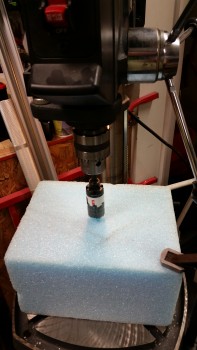
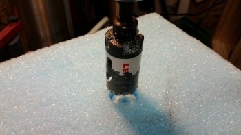
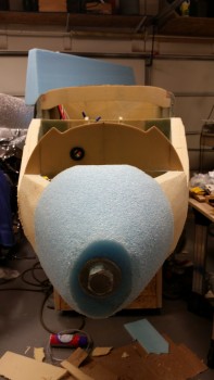
With my foam block in hand, I decided to use a large bolt to clamp it in place.
I then drilled out the center of the block with a 1-1/4″ bit.
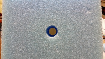
Here’s a closer look.
And the final result.
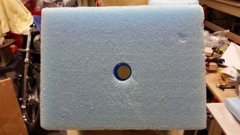
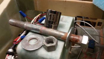
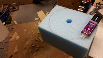
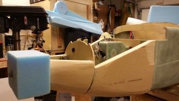
I then mounted the foam block tip to the front of the F-7.75 bulkhead by first applying 4 dabs of 5-min glue first, then bolting it in place to act as my clamp. To make things just a tad EZ, I will use the large washer on the front tip as the “sand to” line for shaping the front nose tip.
I used 4 dabs of 5 min glue to attach the foam block to F-7.75 and to help stabilize the foam block while I shaped it. Obviously I have a hefty bolt through the middle of the block, but I want to avoid any twisting or rotating slippage as I applied sanding force to shape the block.
Here’s my new nose below. Nice look huh?!
Eventually I plan on removing the nose piece after it’s shaped to gain access to the inside area to get the heated pitot tube, landing light install, light housing & heat shroud all squared away. I’ll then flox the entire nose tip assembly back onto F-7.75 before glassing the lower nose.
I then carved the nose tip down to get it closer to its final state. There’s still a long way to go of course, but I just wanted to get the major excess foam bits removed before I called it a night.
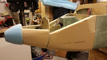
Here’s another look (with Napster peeking up from behind…)
Tomorrow I’ll work a fair amount on the overall shape of the nose, and of course work on the front nose tip. I’ll also be finalizing the install plan for the heated pitot tube.