
…. for the battery that is.
I started today by pulling the peel ply from last night’s layup of the nose battery compartment floor pans. I then razor trimmed & sanded the edges of the 2-plies of BID.
On the right side I spent a good 45 minutes cutting the glass from the bulkhead cable access holes that where drilled through Napster. On the hole for the big cables especially I had to do a fair amount of trimming and sanding to get the grommet to fit. Actually, I also had to trim a little bit more off of the grommet for it to fit.
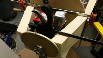
I then remounted the 30A inline fuse to ensure it fit, which it did fine.
In addition to simply remounting the inline fuse, I quickly set the battery in place to double check that the clearance was good between the two.
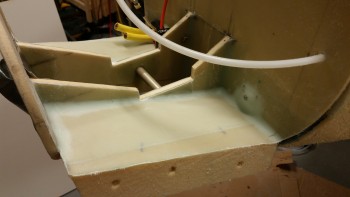
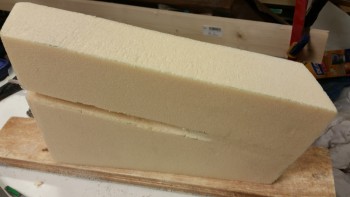
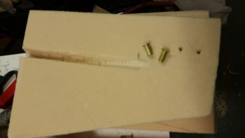
With the floor pans good to go, I then started working on the side walls. I spent a decent amount of time locking in the angles and dimensions, and started on the left side wall. After getting the sidewall cut & sanded to fit, I was then able to cut the channel for the pitot tubing coming in from the F22 area.
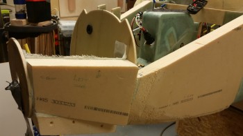
Here’s a shot of the side wall in the orientation it will be in when installed.
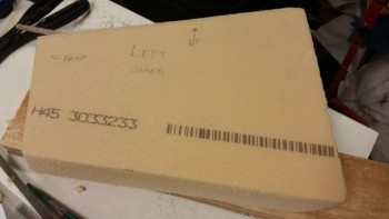
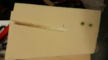
And here’s the shot of the outboard side of the battery compartment left side wall.
I then ran into an issue. which would have been a problem had I not been able to remedy it quickly! ha!
As I’m sure you know, I have a retractable pitot tube. The in & out motion of the pitot tube requires a little bit of flexibility in the pitot tube line. Unfortunately, I miscalculated just how tough (READ: “Inflexible”) 1/4″ Nylaflow tubing really is. In my initial test, I cut the overhang on the pitot tube line and installed it into the pitot tube’s quick disconnect fitting. It fit fine if I were only going to leave the pitot tube in the extended position. But when I tried to push the pitot back into the nose to its retracted position, WTHO? … I might as well have had it attached to a 2×4 vs the Nylaflow. This was NOT going to work. (Remember I mentioned yesterday about “assumptions” …. hmmm, ooops!)
I grabbed all the related fittings I could find, the piece of Nylaflow I just cut off and the pitot tube and headed upstairs. I spent about an hour in research mode checking what pieces parts were available and working through different machinations of how I could configure this thing. Besides merely the flexibility of the tubing, the angle of the sidewall meeting the F-7.75 bulkhead was a bit of a challenge in just how to angle the fittings to get this thing to work.
Luckily, my curiosity worked out this time. I had ordered a couple of the black nylon barb fittings early on in the build to see how they would work in the pitot/static system . . . before I knew about the quick disconnect assemblies that Stein sells. Then, as I was working the through my pitot & static line requirements before installing the pitot tube line in the nose side panel, I ran across a note in the Trio autopilot installation manual that stated 1/4″ Tygon tubing from McMaster-Carr could be used. Well, it would just so happen that not too long after that, I had an order in at McMaster Carr that was a couple dollars shy of their minimum $40 order requirement. Luckily, I remembered the Tygon tubing and ordered a couple feet, again more out of curiosity (and to meet the $40 limit) than anything.
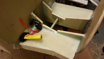
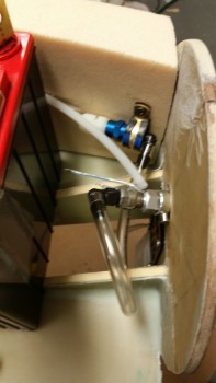
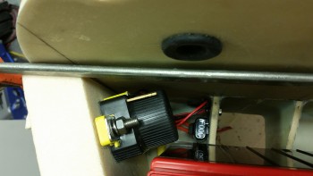
Ahh, serendipity at its finest. So, I pulled the quick disconnect fitting and replaced it with the less sexy black nylon barb fitting. I used the vastly more flexible Tygon tubing as a looped cross connect to the Nylaflow, which of course required a quasi jungle of fittings for the connecting of two non-homogenous lines. This of course mandated securing those fittings to the sidewall: enter Adel clamp, enter RivNut . . . and exit my EZ-PZ pitot tube connection, stage left! (As you can tell simply by the sheer number of words spent on this topic in this post!)
But enough words . . . I probably could have simply provided you with the below pic and you could have derived all I said out of it!
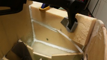
Ok, back to some real work. I snapped this shot since it was the first look at the finished sidewall shaped to fit in place.
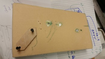
I drilled out the holes for the 2 Rivnuts for the pitot tube line fitting assembly. If you’re wondering why there are 2 Rivnuts so close together, it’s because I have 2 possible options for fittings, and I want to allow for both of them.
[Note: For you sky-is-falling naysayers out there that say I’m doubling the weight by adding another Rivnut, you might like to know that that I can’t even get one these things to register even a gram of weight on my scales … and I said that in the plural because I have 3 scales, and each one shows the weight of the Rivnut as a whopping “0” grams.]
I then mounted the Rivnuts in the holes.
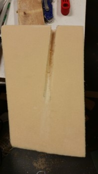
I then matched the right side wall panel foam blank with the left side and marked up the right side as a mirror image to the left. After cutting the right side panel and sanding it to fit, I mocked up both panels to verify the fit of the battery.
I also checked to ensure that I had a good amount of sidewall foam in contact with the bulkheads and the floor. Now is probably a good time to mention that the aft lower corners of these side walls, at the intersection of Napster & the floor pan, looks a bit narrow. I may end up adding a bit of filler material if required, but I’ll wait and see if it will be needed.
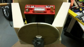
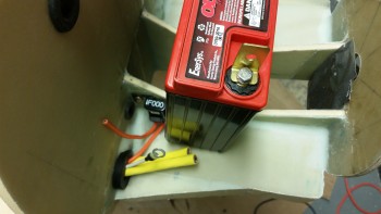
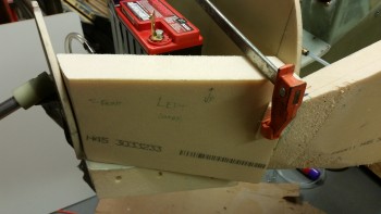
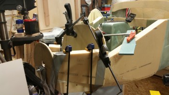
To keep the sidewalls on their marks, I pulled in the aft side of the walls and expanded the front . . . it all looked good. (You might notice the dixie cup taped to the battery post. I didn’t want to inadvertently leave a metal clamp resting against those tall vertical battery posts and fry my expensive battery . . . or cause any smoke.)
I then got to work on finalizing the installation location & orientation of the battery contactor. As I’ve said literally a gazillion times, there is not a lot of usable space in the nose, and the battery compartment is big enough for all the stuff I’m putting in there . . . just barely. Also, to atone for my sins of dishing out the NG30 compartment nose side panels, I’m leaving these battery compartment side panels straight, primarily since I have no reason or requirement to dish them out.
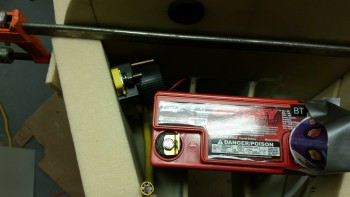
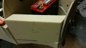
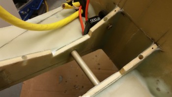
After playing around with the contactor positioning a bit, which included a constant in & out with the main battery, I figured out where it needed to go. Below is a shot of the final contactor installation spot. BTW, if you’re connoting aloud to the computer that I clearly have no idea how to install a contactor if I’m mounting it sideways, then I’m happy to report that that’s exactly one of the primary reasons why I’m using the Gigavac GX-11 battery contactor. Not only can it be mounted in literally any position, but it also consumes less than a 1/10th of an amp to keep it closed (vs the normal 1 Amp draw).
This wasn’t my first choice or preferred orientation of the contactor, but it will work fine. It did cause me to have to bring the big power cable forward and loop it back in order to get the cable’s connector angle correct. This of course mandated securing the long length of cable to the sidewall. Another Adel clamp.
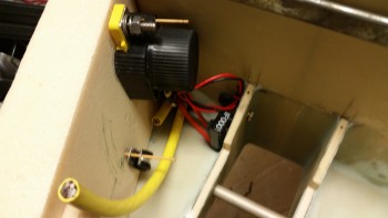
The contactor mounting location exercise, and subsequent requirement for an Adel clamp, got me to assess my cable management requirements. I would be bringing wires in from the very front of the nose, from 2 lights, a heated pitot tube, and the gear back-up battery, in addition to mounting my TCW IBBS on the left side of the battery compartment. These all add up to a fair number of wires in & around the battery compartment. Clearly it would be grossly irresponsible of me not to keep these wires under wraps (pardon the pun!).
So, as I was prepping the left side panel for its install onto the nose, I added another Rivnut to the lower side panel.
Then, to get the orientation of the Adel clamps aligned parallel to the wire runs on the front & aft side of the battery, I drilled 3 Rivnut mounting holes into the edges of the BC1s where I had determined that I would need them.
After this nitnoy stuff was out of the way, I whipped up some thick micro and mounted the nose battery compartment left side wall into place. For some reason (how many times do we say this to ourselves?!), however great the side panel fit when I was mocking it up, it really became a pill when I was mounting it for real. I pulled it out and re-slathered it with all the micro that had oozed out everywhere and that I had collected back in the cup. I then remounted it in place and then clamped that sucker to keep it in line.
I let the micro cure a bit as I cut 2 pieces of BID off the spool for each side wall. As you can see, I also mixed up some fairly dry micro and buried the pitot tube line with it. My goal of course was to get the pitot tube line channel even with the surround foam.
After cutting 2 plies of BID for each side wall, I then laid up the left side wall using fast hardener. The layup went ok, but since the micro was well into the green stage –since I had let it sit longer than normal due to the clamps holding it in the correct position– it was stubborn in holding its less than perfect fillet shape. The fillets were somewhat distorted due to the movement of the sidewall before I finally clamped it in place. A minor oversight that I didn’t rework them, and as I was laying up the BID, it became a minor annoyance.
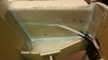
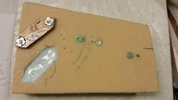
Here’s an outboard shot of the curing, glassed left side panel.
With the left side panel install layup curing, I went to work on the right side panel. I added another couple of Rivnuts and then started working on the battery contactor mount. I first cut off the corners of the 1/4″ Finnish Birch plywood (same that’s used for the firewall) mount in which I have the M5 Tee Nuts installed. I then used the plywood contactor mount as the template to cut out a 1/4″ deep cutout in the foam sidewall.
Once the cutout was good, I cleaned it out, whipped up some flox and mounted the battery contactor mounting plate in place.
I then laid up the up the right side panel with 2 plies of BID and peel plied the entire panel. I guess here would be a good point to say that, unlike the left side panel, I will be glassing in this side panel the way my buddy Marco glassed in his main nose side walls: glass them first then install with BID tapes later. I’m doing it this way mainly because of having to install the battery contactor mount. I didn’t want to mess around with that while concurrently attempting to layup 2-plies of BID vertically in a cramped space. So I minimized my variables.
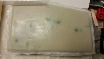
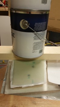
On my right side nose panel layup there was a very slight mound of flox over the battery contactor mount that I wasn’t successfully able to level out with the squeegee. So instead of making things worse, which I have an incredible knack for, I simply put some plastic over it, laid a large piece of wood on the plastic and weighed all that down with 2 gallons of paint. That should do the trick!
Tomorrow I’ll clean up these layups, get the right side wall glassed in and then start work on the very front of the nose. Slowly but surely it’s getting there. I’m thinking my fine looking nose is just around the corner!