Better buckle up boys ‘n girls, this one’s gonna be a long one!
I started out by pulling the peel ply and trimming the glass edges on the nose battery compartment section cover. I test fit it back in place and it still fits like a champ.
I then pulled the peel ply and trimmed the glass edges on the left and right interior nose sidewall extensions layups. I cleaned up all the peel ply boogers and inspected the layups.
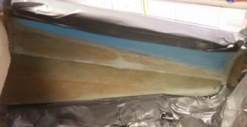
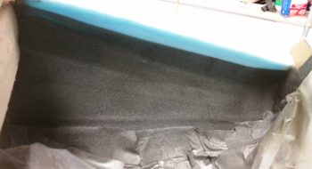
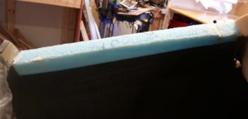
The layups themselves looked good and were of good quality, but I couldn’t get past the menagerie of varying colors, foam types, etc. I simply did not want that staring me in the face every time I opened the nose hatch. And I checked to see if these sides would be visible with the hatch open, and from what I could ascertain in my mental mockup it was a definite yes.
Since I already had a plastic cover in place to protect the nose components from all the nasties produced during the construction of the nose, I simply pulled the sides and move the tape line to just below the existing visible speckled paint I had shot before. I then spent about 10-15 minutes adding a bit more protective barrier and tape, including the top side edges of the new foam sidewalls that I had just glassed.
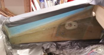
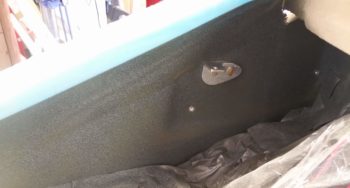
I then hit the just-glassed interior nose sidewalls with a light coat of primer and a couple light coats of speckled paint. Ahhh, HUGE improvement. So, so, so much better!
I then remounted the pitch trim actuator bracket… if you compare this pic to the one above of the same sidewall…. wow, no contest. I’m very glad I decided to take a half hour to remedy those eyesores!
I actually did a bunch of the following while the primer from my painting effort above dried, at which point I took a couple minutes to shoot the final speckled coats.
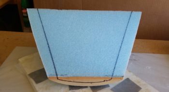
I measured the current sidewall widths both at the front and aft ends to then transcribe those sidewall widths onto the bottom of the nose battery compartment foam cover piece.
I then marked up the sidewall widths going up, as you can see on the aft side of the foam base of the cover here.
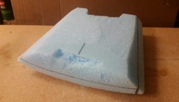
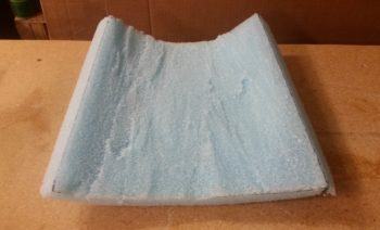
I then started dishing out the extra foam on the bottom side of the nose battery compartment cover. As a point of note and as I explained a couple of blogs ago, this step would normally be done AFTER the entire nose had been glassed and the builder was shaping the internal side/top wall of the nose to then create the edges in regards to the hatch. Again, due to the bulkhead in the middle (Napster) I’m doing all this before I glass the entire nose.
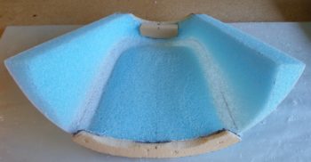
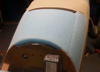
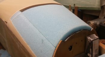
I then got to the final rough stage of foam removal on the nose battery compartment cover.
And then did a final sanding to smooth out the interior walls/top.
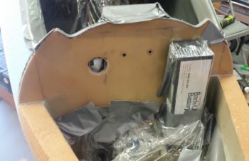
I then put the IBBS in its mounted position to check for not only clearance with the interior nose battery compartment cover walls, but enough space to mount and unmount the IBBS unit.
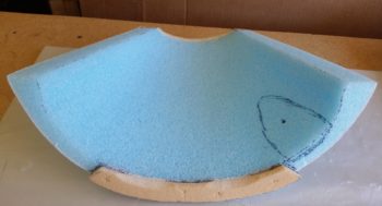
The black dot is where I marked a slight indentation from the corner of the IBBS pressing into the nose battery compartment cover interior foam surface. I then marked an area around the contact point to give the IBBS a bit more room for ingress/egress if required.
I then carved/sanded the clearance required for the IBBS unit.
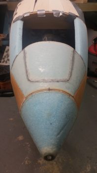
I then marked up the forward dimensions of the nose hatch door onto both the exterior (glass) and interior (foam) surfaces of the nose battery compartment cover. I realize the nose hatch outline looks a bit off center in the pic below, but it must be an illusion created by the camera angle, because I rechecked all the dimensions from centerline and it’s both asymmetric overall and equidistant from the centerline.
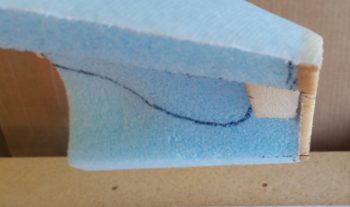
I also carved out a small notch at the very front of the nose battery compartment cover to then insert a small piece of H250 high density foam. Since I’ll have only one larger nose hatch that is attached via hinges at the front end and by one latch at the aft end, I want to ensure the front side is very securely fastened and the darn thing doesn’t blow off the aircraft, thus the high density foam plug insert at the front edge for added strength. It may be a bit of overkill, but I’d rather not wonder about the security of my nose hatch door!
I then had to angle the bottom edge of the H250 high density hinge attach hard point so that it was pretty much level and parallel with the waterline of the aircraft.
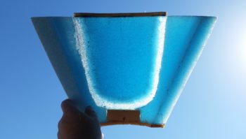
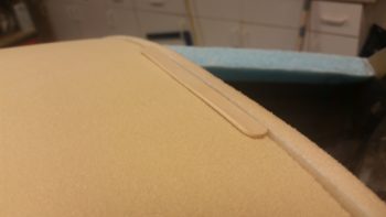
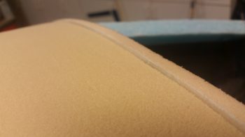
Since I carved away the nose hatch marking on the foam, I wanted to check exactly where the nose hatch edge line was, so I took the piece outside to check it out in the sun. I could actually see the line in the shop, but thought this was a cool pic once I took it.
I then carved both the nose hatch door foam and the adjacent nose battery compartment cover interior foam down to create a gradual slope to where a lip will be created for the nose hatch door. Now, I’m not really concerned about the actual nose hatch door foam here, since it will get its final shaping done when connected to the aft 2/3rds of the nose hatch door which will be positioned aft of the Napster bulkhead.
My main concern here was the nose battery compartment cover interior foam, both the transition of the foam and the width, position and quality of the glass along the foam edge. I had meant not to micro the foam when laying up the 1 ply of UNI on the external side of the foam, but didn’t remember until immediately after I had slathered on all the micro.
Thus, with a really rough surface to contend with, I took the piece out back and spent 15 minutes with the Dremel Tool carefully knocking off all the micro crud from the glass. I then sanded it smooth with a Perma-A-Grit tool and called the glass surface acceptable for a glass-to-glass bond.
Since there is not a lot of sidewall here on each side of the nose hatch door opening, I opted to add another ply of BID to each side for added strength. It’s not like there’s that much real estate to really make a huge impact on weight, and I figure this is also somewhat of a structural area simply in regards to the nose structure as a whole, and specifically for the constant swinging action of opening and closing a rather large nose hatch door. I also added a couple of rectangular plies just over the H250 high density foam hinge mounting hard point.
The methodology that I’m employing here is that I am simply creating the lip of the nose hatch door now vs later. The 3-ply nose battery compartment cover sidewall glass simply crosses and is glassed to the narrow bare glass threshold to then overlap onto the taped foam surface of the nose hatch door. To be clear, the line for the nose hatch door goes pretty much down the center of this bare glass threshold.
The KEY to ALL of this is that when I cut the line for the forward side of the nose hatch door, I must be very careful and cut just through the top glass and not all the way through… which would negate all the work here and I would simply lop off the lip I have just created. As insurance I added another ply of BID around 1/2″ wide to just below the nose hatch door outline.
I then of course peel plied the edges of the layup.
While the internal nose battery compartment cover layup cured, I then got to work on the what will be the back “half” of the nose hatch. I will work this side of the nose hatch in a more traditional manner in that I will remove a piece of the nose with a few added inches around the marked nose hatch line, create the edge of the nose hatch hole & door, glass the piece, then return it to the nose for final glassing.
To do what I just described I’m essentially just removing the big center foam nose plug I created yesterday. Yes, I know it’s better for bonding to glass multiple plies of glass all in one go, but here I don’t really have a choice (as I see it) if I want to make this single larger nose hatch a reality. Thus, I won’t even micro in the big center foam nose plug when I lay up the initial single ply of BID on the nose. I will simply mark the edges with a Sharpie to make it visible and then cut it out once the glass has cured. When I do cut out this big center foam nose plug, I will also CAREFULLY cut out the then attached forward nose hatch door piece from the nose battery compartment cover. It will probably look like a big blob of glassed foam with a giant fingernail sticking out!
To set myself up to make all this as easy as possibly, I wanted to dial in the general shape of the interior of the big center foam nose plug. I determined the widths of the adjoining sidewalls and marked them up on the foam plug.
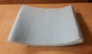
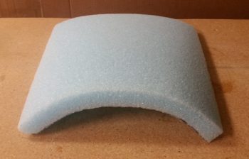
I then removed all the extra foam and rough shaped the underside of the big center foam nose plug.
And then hit it with a round sanding block to get a smooth surface on the underside, which besides the required depressions for the edge of the nose hatch, completes the major foam shaping –both internal and external— for the nose!
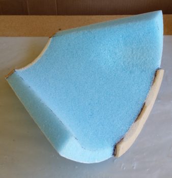
Here’s a view of the big center foam nose plug right side up.
I then of course test fitted the freshly carved (underside) of the big center foam nose plug. Looks like it will work (fingers crossed!) . . .
With the front half of the nose pretty much squared away and nearing completion… after the internal nose battery compartment cover layup cured, I then set my sights on the aft side of the nose: the cover.
The first order of business was to sand a depression on the entire front side of the urethane foam plug that abuts the aft side of the intermediate bulkhead. This depression –or elevation adjustment– is required to help match up the nose glass level between the aft side cover and the front side nose glass. Since a layer of tape, then a couple plies of BID followed by strips of 1/16″ thick Basswood will be employed to create the base of the aft nose cover, I transitioned the urethane foam plug to be a bit deeper than a narrow mixing popsicle stick (~ 0.080″).
Here you can see the depression below the edge of the intermediate bulkhead.
After some more pondering, thinking and assessing, I then made the command decision to move the break line between the forward canopy opening and the nose to intersect with the angled edge of the aft nose cover right at the sides where the angle ends and transitions into a small length that traverses aft to intersect with the outboard ends of the glare shield… this segment is just along the top of the longeron for a few inches. This will allow the canopy skirt to cover up (hide) the cover segment along the longerons and will give the appearance of a converging 3-line intersection: ONE single line along the longeron, the canopy break line across the top of the nose, and the angled aft-up-sloped cover line. Think of a sideways “Y” for visualizing it a bit better.
I had originally envisioned the front break line of my canopy to be a bit more curvy and sexy, but decided to make it a bit straighter across the front with some curve at the outboard edges. I think this will be cleaner and simpler, allowing the lines to flow better visually, especially when the canopy is open since the canopy break line will parallel the glares shield lines. It also makes constructing the cover and canopy skirt considerably easier since I don’t have to carve/match a more detailed curve for the break line.
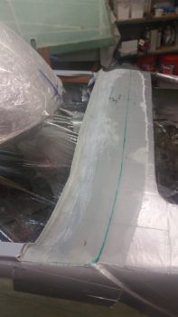
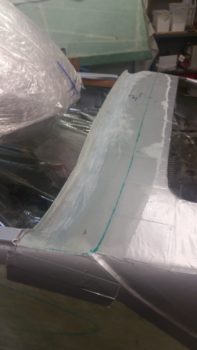
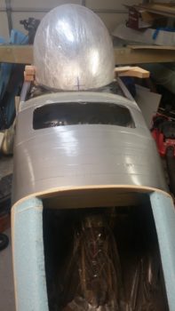
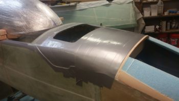
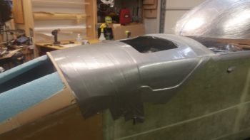
I then finished duct taping the aft nose for the eventual cover glassing. Rest assured, since I went through great lengths to minimize the depth and thickness of the tape (read: 1 ply) this took a fair bit of time and effort.
I also cut some glass away from the outboard edge of the glare shield layup to reglass it with the aft edge of the lower angled cover depression dialed in this time around. Here’s some side views of the taped up aft nose ready for some glass to create the aft nose cover.
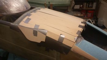
To bridge the obvious Grand Canyon sized hole I have in the top of my aft nose area, after weeks (actually years) of thinking I decided to go with thin, fairly flexible 4″ wide strips of Basswood… which is very close to Balsa wood in characteristics, just a tad denser and a little less fragile. It is still very lightweight nonetheless.
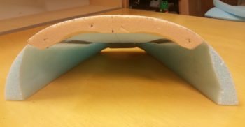
Here’s a quick shot of the Basswood measured to length and shaped to be mounted to the aft nose surface to create the cover. I know it looks a bit in rough, raw form, but when secured in place they will flow together and create a much more uniform shape than shown here. Also, I didn’t get a close up shot of it here, and it may not be readily apparent, but the aft edge of the combined Basswood strips make up the raised edge on the cover side for the break line with the canopy skirt.
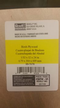
The more detailed piece of wood that makes up the cover’s edge inside the sidewall depression (shown above) is a slightly thinner piece of 1/32″ Birch plywood.
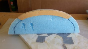
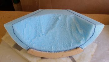
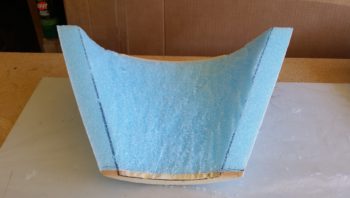
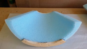
It was very late so I did one final push for the evening to finalize the preparations for both the front and aft side nose sections for glass. By this point the internal nose battery compartment cover layup had cured. Not 100% (thankfully!) and was still just pliable enough for me to razor trim the edges with a knife. I also pulled the peel ply and cleaned up the edges and all the peel ply boogers.
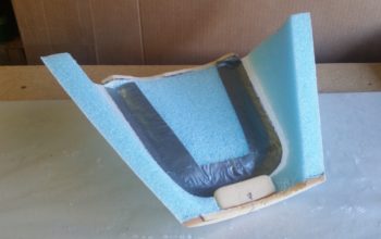
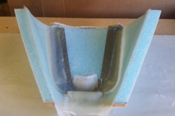
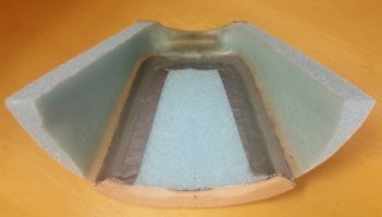
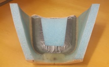
The layup looked really good and looks like it will work according to plan. Here’s an internal shot of how it will look from the aft side once it’s installed in place.
I then of course had to test fit it back in its place on the nose.
Looking pretty good!
With that, both the forward and aft nose sections are ready for their initial rounds of layups. It’s really late… so I am calling it a night!

