
I got a late start today so I didn’t get any sanding in. I did however get a lot of stuff done. In all actuality I would call today an R&D day. Although it probably doesn’t reflect it in the pics below, but I spent a decent amount of time online and standing there doing my best Winnie the Pooh impersonation: “Think, Think, Think” followed up with, “Oh, bother…”
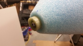
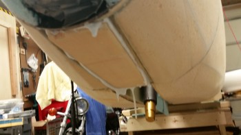
Below is a shot of my officially mounted nose cone. Thus completing the major section construction of the Davenport nose!
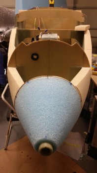
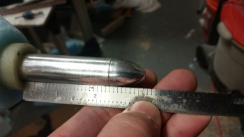
I had to throw in the pitot tube just for style points!

And here’s another shot. Think that angle looks a bit odd . . . so do I to tell the truth. Note my alignment tick marks around the aft edge of the nose cone.
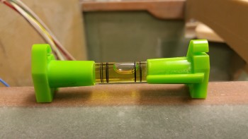
But check this out: here’s a level on the longerons . . .
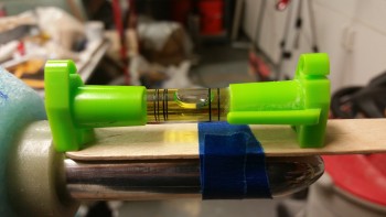
And here’s a level on the pitot tube. You can’t get much closer than that!
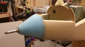
If you’re curious (I was), the pitot tube sticks out of the G10 sleeve right around 3.15″.
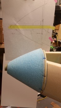
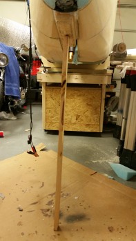
And here it is in Airport & Fly-in mode, where, you know, certain types of people like to blindly step on expensive parts of your airplane while it’s in grazing mode.
I drew up this plan for the nose cone area and pitot tube in the April/May timeframe of 2013. I just think it’s really cool when a plan works out.
I wanted to get to figuring out the taxi light. To do that I needed to take out the gear strut so I could get a good look at the NG6B pivot assembly. Since I was working in the NG30 gear box anyway, I popped the aft cover off to reset the up-travel limit microswitch. Since I’m none too bright, a few weeks ago I meant to set it so that it wouldn’t raise up so high into the wheel well, went the wrong direction with the microswitch, and ended up making it go too high … where if I didn’t stop it, it wanted to make some minor crunching noises. Not good. Plus, I needed to add locknuts onto the new long screws I put in since when I bought those screws they only had the standard ones.
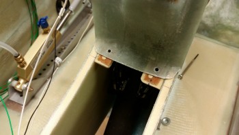
When I took out the gear strut and gently lowered the actuator gear tube down to the mount cross strut behind I couldn’t raise up the gear when I flipped the switch just a few minutes later. I checked the battery because my buddy Marco had an issue that he discussed with Jack where he didn’t have enough juice to power the thing. My battery was down to about 12.65 volts, so I put it on the charger and grabbed my bench top 12V battery and tried it. No joy.
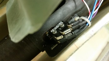
Ok, something was up. Well, it took me less than a minute to see that a couple of wires had pulled off of the gear up limit microswitch, as you can see in the pic below (behind the blue wire to the right). Obviously this happened when I lowered the actuator down to its lowest point, but why? As I started messing with the wires I saw that the zip tie holding the wires in place (the white one visible in the pic below) was really loose. I then checked the other side and it was just as loose. So in the immortal words of Steve Urkel, I said, “Did I do that?!” . . . well, the answer was yes. Apparently, I forgot to tighten them full tilt after I wired up the added gear up/down alarm wires.
But I learned something about this system, it’s critical that you have a 0.15 cent zip tie secured correctly or mayhem may ensue. I don’t think those small fast-ons have a ton of gripping strength, so putting a zip tie behind the connector flanges and into the heat shrink works as a failsafe to keep those wires where they’re supposed to be . . . on the tabs.
Anyway, problem solved.
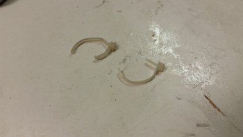
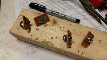
Here are the culprits:
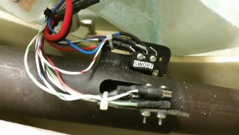
And here’s the new zip ties in place and secured correctly.
From there, I moved on to something that has been on my list of things to do, but quite honestly I just haven’t been motivated yet to knock it out. Actually, it’s 2 very closely related tasks: mount the forward NG30 cover, and mount the Parking Brake Valve.
My plan for this evening was to get this low-hanging fruit off the list, then I would sit & ponder how I was going to configure the taxi light system. I need to know how the taxi light is going to fit into the overall scheme before I glass the exterior nose.
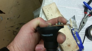
I used my mini-router base on my Dremel to measure the width of the Phenolic (I knew it was 1/16″ but this was easier).
I then marked my area of destruction in blue. I shaved off a 1/16″ in the blue area to fit the parking brake nutplate assembly (sorry no pic).
I then mocked it up to see if it worked. All was looking good!
I then drilled my aft (to the right) #6 screw holes and my forward #8 screw holes and set the screws in place to see how it looked.
I then made up 2 x #8 nutplate assemblies and 2 x #6 nutplate assemblies using 1/16″ phenolic as a base.
I then 5-min glued the #6 nutplate assemblies to the NG30 inboard top edges using the screws and the covers as a guide (I taped up the bottom of the aft NG30 cover so it wouldn’t get any 5-min epoxy on it …. sorry, no pic again. I was really trying to get this stuff knocked out so I guess my picture taking was lacking). BTW, the nutplates are embedded in H250 foam pieces, so it took me a bit of time to prep those bad boys.
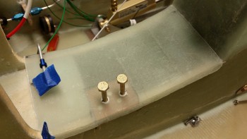
With the #8 screws on the forward side (to the left in the pic below) I merely drilled a hole through the forward NG30 cover and the draft plate right below it and then 5-min epoxied the nutplate assemblies right to the draft plate underside. When I flip the fuselage to glass the nose I’ll glass in all the nutplate inserts I’m installing tonight.
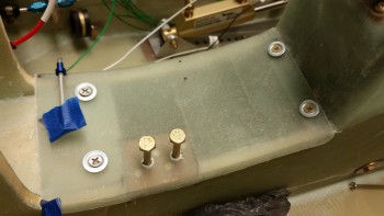
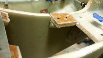
After the forward NG30 cover mounts were completed, I turned my sights onto the parking brake mount. Earlier, when I glued the aft screw nutplates of the forward NG30 cover, I also 5-min glued the parking brake double-nutplate assembly to its H250 foam base. At this point below, the nutplate & foam were one unit and the foam piece to the left a wedge shelf made up of H45 Divinycell foam (spare nose foam) that acts as a shelf for the quasi-cantilevered parking brake nutplate mount (I say “quasi” because less than 0.1″ of the front edge of the phenolic overlays the aft edge of the draft plate, offering a decent amount of stability).
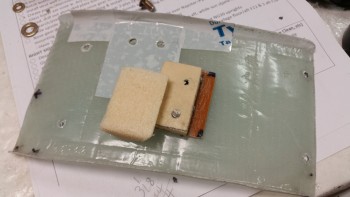
Here’s the parking brake nutplate assembly mount after it cured.
In this shot you can see the PVC foam wedge shelf below the H250 foam base on the parking brake mount.
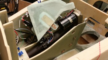
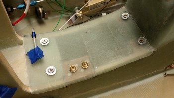
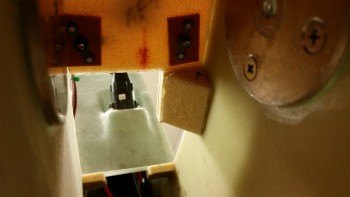
I like this shot because you can see the major tasks I was undertaking this evening for the forward NG30 cover and the parking brake mount. In the middle of the pic you can clearly see the PVC foam wedge for the parking brake mount. You can also see the 2 #8 nutplate assemblies for the forward screws at the top of the pic. Again, these were simply 5-min glued to the underside of the draft plate and held in place tightly with the screws. And you can kind of make out the aft #6 nutplate assemblies at the bottom of the pic.
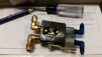
Since the forward NG30 cover is both curved and a hard surface, I didn’t want the Parking Brake Valve sitting right on top of it. I grabbed some peel-n-stick black industrial felt that I had laying around and cut some holes in it, peeled off the backing and prepped the PBV for mounting.
Here’s the peel-n-stick felt in place on the parking brake mount.
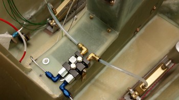
And here (FINALLY!) is the parking brake valve hard installed onto the forward NG30 cover which is now hard installed as well! Hoo-ah!
And then guess what?! While looking for something completely unrelated, I found a bag of 10-32 sized Rivnuts! I’m happy I found them, but Arghhh! I could have already knocked some stuff out if I had known these where here. Exactly why I brought up inventory control before!
So, what I didn’t mention yet, was that there will actually be another point to help secure the forward NG30 cover. However, this hard point will be dual use with a concurrent purpose of securing the Adel clamp for the hole C wire run coming from the battery compartment.
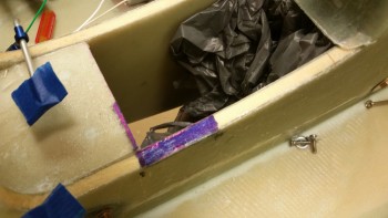
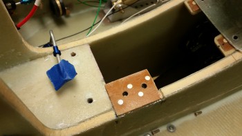
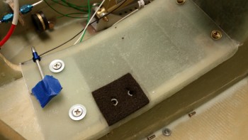
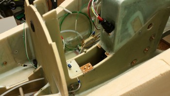
Also, I can mount the 3rd Rivnut in the battery compartment. In the pic below there are 3 notable things: 1) the aforementioned Rivnut in the battery compartment, 2) the Rivnut set in the freshly drilled hole on the right NG30 edge about midpoint of the forward NG30 cover, and 3) you may note by the last battery compartment Rivnut there is a 3/16″ Nylaflow line traveling from the battery compartment into the NG30 gear box. This tubing will house the taxi light assembly actuation cable from the NG6B to the taxi light assembly. I spent a good 20 minutes figuring out where this cable conduit hole needed to be drilled.
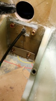
Speaking of taxi light, once I had the location of the cable conduit hole, I could proceed with installing the H100 center battery compartment floor piece that connects the 2 BC1 plates. But first I had to install the upper taxi light hinge half. I whipped up some flox and slathered up the back side of the hinge and then installed it using thick washers and standard aircraft grade nuts.
Then, with that flox I also installed the 2 newly found Rivnuts.
I then mixed up some thick micro and installed the H100 foam center floor piece of the battery compartment. With this piece installed I’ve officially mounted every bit of foam for the nose build!
Since I’m not glassing this foam tonight, I kept the micro fillets in the corners to a minimum.
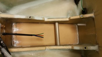
Here’s a shot right after I installed the foam piece. There’s definitely a good amount of micro, eh?!
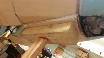
Then, knowing my luck, I wedged a couple of pieces of wood underneath the freshly installed H100 foam piece to ensure it didn’t decide to follow the laws of gravity and just plop out on me in the middle of the night!
Here’s a closeup of the wood wedge securing the foam in place.
Tomorrow I plan to work extensively on the cable attachment assembly & configuration for the taxi light. Early this week I should get the mount for the taxi light so I can construct the hinged mount. Even though I’ve started on this a bit, I’ll be working more to prep the fuselage for getting flipped here in most likely the next few days. Which reminds me, I’ll also be working on the wheel well cover (NB) since I need to glass that in place too before I flip the fuselage.
My goal is clearly to finalize everything that needs completed BEFORE the fuselage gets flipped upside down, then flip the fuselage ONCE to finish the bottom glassing and then press on with the main gear and main wheel/brake install from there. Any item that I haven’t finished in the nose area after I flip it upside down will be considered a long term task that can wait 3-6 weeks before the fuselage gets flipped back upright.