
I started today by trimming the sides of the Voltage Reg Click Bonds that were overhanging the edges of the F22 both on the top and the bottom. I used a cutoff wheel on the Dremel tool and then followed up with the hard sanding board.
The top Click Bonds stuck out about 0.1″ above the F22 while the bottom Click Bonds overhung the bottom edge by about 0.2″.
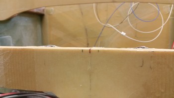
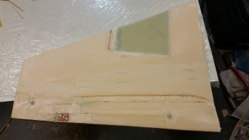
Here’s the top F22 edge free of Click Bond overhangs. [While writing up this log section I realized I didn’t get a pic from the other side… I’ll try to include one tomorrow].
I then started back on prepping the right side foam nose side wall for installing onto the existing airframe.
It took well over an hour to finalize the positions of the nutplate & RivNuts that I would be installing as mounting points for the rudder pedal cable bushing, and 3 Adel Clamp mounts: 1 for the brake line & 2 for the main power cables.
I then spent another 45 minutes on researching and figuring out exactly where the Atkinson Pitch Trim Actuator would get mounted. It took a few iterations, and a few possible locations to lock in a final location (which of course happened to be what I had initially planned).
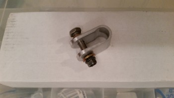
There are two distinct requirements that I’ll be meeting in prepping the right side wall for the pitch trim actuator. 1) I’ll be laying up 4 plies of BID under the regular 3 plies of BID for the interior sidewall skin. 2) The pad for the 4 plies of reinforcement BID (and thus the pitch trim actuator mounting base) will be in a depression that is angled at the front to make it (and, again, the pitch trim actuator) aligned more parallel with the CL of the airplane. I’m already messing with the mount between the trim actuator arm and the elevator control tube by having to bring it farther forward about an inch more than what Vance calls for, but I’m not overly concerned with that since my buddy Marco made a clamp-style connector that is less intrusive and thus less stressful to the elevator control tube (e.g. no drilling a hole through the tube). It also makes the actuator to control tube mounting point naturally lower since it’s a clamp style, which works better with my angles. Marco’s clamp is shown below.
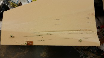
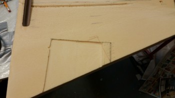
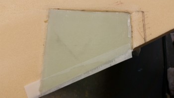
With the design plan set for the pitch trim actuator mounting pad, I took the right side panel out back to router the major foam out of the depression area. At the shallow end I routered 0.1″ deep.
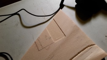
And at the forward half of the depression I deepened the router cut to 0.2″.
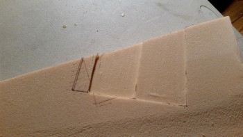
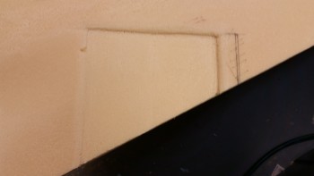
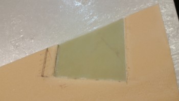
I then took it back in the shop and sanded the bottom of the pitch trim actuator pad depression to level & smooth it out.
And sanded the edges to give the sides a nice radius for the glass to flow smoothly over.
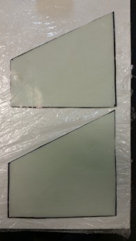
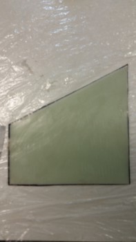
I got into my glass cutting table to cut out the 3 pieces of 3.5″ x 7″ BID for the F22 corner reinforcement layup that will be one of the final steps when I lay up the right nose side panel. I also cut 2 pieces of BID measuring a little over 6″ x 9″ for the pitch trim actuator pad, which I prepregged below.
I mixed up some epoxy with fast hardener and wetted out the 2-ply prepregged BID.
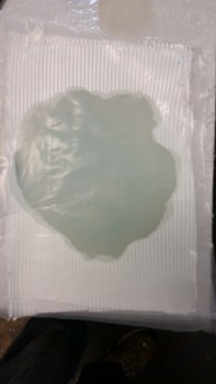
Although I only wet out 2 plies of BID, I’m actually cutting it in half to make for a 4-ply BID layup. I know! Clever huh?!
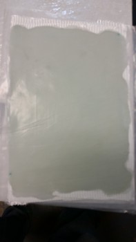
I first marked up the prepreg plastic, and then cut the perimeter.
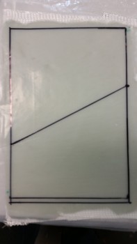
I then cut down the diagonal line to make 2 pieces that were nearly identical. Of course I then combined those two separate prepreg pieces to give me one 4-ply prepreg setup.
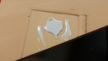
I had already mixed up the micro slurry before I finished marking & cutting the prepregged BID, so I used that to prep the foam in the pitch trim actuator mount depression.
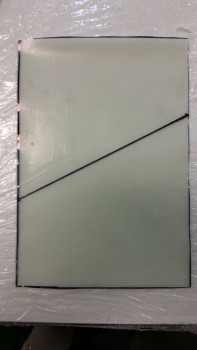
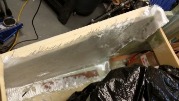
I laid up the 4-ply BID reinforcement pad and used the top plastic to drive out all the air bubbles, getting it to lay down really well.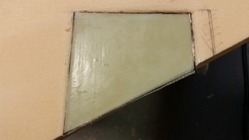 I then pulled the plastic & peel plied the layup.
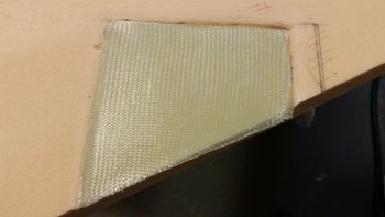
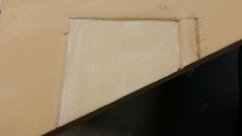
Here’s the same layup a couple hours later after I pulled the peel ply.
With the hardpoint nutplates & inserts floxed into place and the pitch trim mounting pad cured, I whipped up some epoxy with slow hardener and made some micro slurry out some of it. I then micro’d all the foam surfaces of the inboard right side nose foam panel.
I did a combo style of layups on the right side panel. I started with laying up only 2 plies of BID before mounting the side panel into the fuselage. I still didn’t wet out the glass below the brake line channel, so after the foam side panel was in place I embedded the brake line in the channel with 4 spots of 5-min glue. I held the brake line in place with toothpicks near each application of 5-min glue.
After the 5-min glue cured, I applied micropaste to the brake line channel to fill in the gaps between the brake line and the channel. After I got the brake line channel squared away, and all the glass wetted out on the first 2 plies, I then laid up the 3rd and last ply of BID.
I think I mentioned this before, but I’ll point out again that normally I would only overlap the BID from the sidewall onto the floor, bulkheads, etc. the typical 1″ that would be provided by using your standard BID tape. However, on the sidewall to floor plan I overlapped the BID by about 2″ in order to use the 3-plies of BID as not just the attachment mechanism for the sidewall, but also as a 3-ply reinforcement base for my rudder/brake pedals bringing the total to 5 plies of BID over each rudder pedal phenolic base.
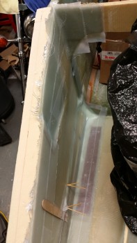
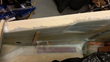
Here’s a shot of the finished layup on the right side nose panel. You can see that i had to leave a couple of sets of toothpicks in to keep the forward end of the brake line & its encompassing glass flat against the foam panel.
Besides the standard overlap of glass across F22 into the forward fuselage area, I also mounted a wedge of foam to serve as a ramp for the 2 large power wires transiting from the battery to the engine compartment.
Here’s another shot of the glassed right nose side panel. You can see the triangular wedge piece at the front of the layup. You can also see some of the pitch trim mounting depression as well.
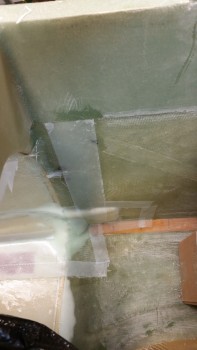
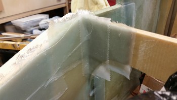
Below is the 3-ply BID layup that gets glassed in the corner for reinforcement of the canard mounting bracket. This is the final step for glassing in the nose side panel.
Tomorrow I’ll pull all the peel ply and clean up the ever-present peel ply goobers. I’ll also drill out the myriad of nutplates and hard points, to include mounting the right rudder pedal. From there I’ll start planning the mounting of the next (and last) bulkhead.