
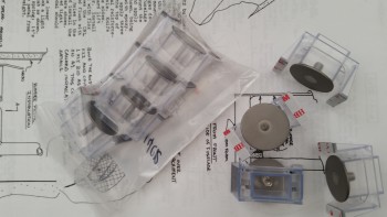
I was getting ready to head down to the shop today to start working on the project when UPS delivered my order of Click Bonds.
I ordered a set of four 10-32 Click Bonds for installing the EFII Fuel Boost Pump and another set of four 1/4-28 Click Bonds for installing the B&C Voltage Regulator to the aft side of F22. The latter would be the first task of the day.
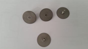
I first removed the Click Bond studs from their plastic installation housings.
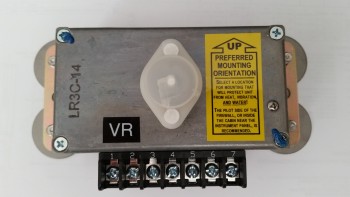
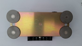
I then test fitted them on the voltage reg.
I sanded the upper aft area of F22 in prep of mounting the voltage reg. I then put together a prepreg setup with 2 full plies of BID and a 2″ strip over where the left and right pair of Click Bonds will be positioned. In the prepreg setup I went ahead and covered the BID with peel ply.
I then wet out the prepregged BID with epoxy using fast hardener, cut a small hole in the peel ply where each Click Bond stud would stick through the BID, cut the prepregged BID to 3″ wide x 8.5″ long, and then attached the taped-up voltage reg to the prepreg setup. I left the top piece of prepreg plastic on, so it remained between the back plate of the voltage reg, the peel ply and subsequent plies of BID.
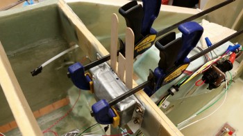
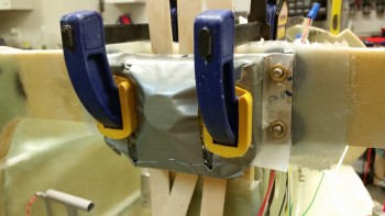
I put a small mound of flox on each Click Bond face, added flox around the edge of each Click Bond for a transition, and then mounted the voltage reg, glass and peel ply assembly to the aft side of F22 with clamps. I used just enough clamping pressure to keep the voltage reg in place and to firmly seat the Click Bonds. I then worked the glass all around to ensure it was laid up well against the F22 surface. Since there was a small gap between the Click Bond studs and backside of the voltage reg, I pressed popsicle sticks in-between the voltage reg and the glass.
As a point of note, the reason why I’m mounting the voltage reg at this point is simply due to the better access I have without the right sidewall in place. I had originally wanted to accomplish this before either side wall was in place, although admittedly it wouldn’t have been that much more difficult to mount if the walls were in place. But the access provided without the side wall in place did make the install easier, and makes the post cure glass trim a lot easier on the right side as compared to the left.
I then trimmed & cleaned up the left nose side wall layup. Below you can see the 3-ply BID layup in the corner. In addition, I drilled & cleaned the bolt holes to mount the left side rudder pedal.
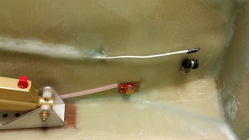
I also mounted the rudder cable end AN111-3 bushing with a short AN3 bolt, and the Adel clamp forward of where the brake line bulkhead fitting will get glassed into place.
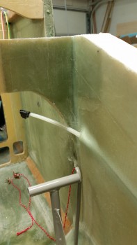
Here’s a shot of the external side of the left nose side wall glassed & floxed in place.
Here’s another shot of the corner 3-ply BID layup between F22 & left nose sidewall. You can also see the embedded pitot line as well.
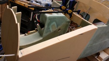
After cleaning up the left side wall and mounting the voltage reg, I then started working on the right nose side wall. The right side has an extra element that must be dealt with: the 2 large power wires that traverse the fuselage from the battery back to the starter & firewall. Since space is really tight in the nose, and especially along the sidewal adjacent to the rudder pedal, I really needed to figure out the placement of these power cables, mainly to know where to embed the Rivnuts for the Adel clamps.
I measured the diameter of the big power cable at .420″. I then found a quick substitute for checking the spacing with an air house that measured .460″ in diameter, providing a bit of extra diameter for some wiggle room.
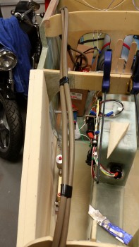
My initial placement of the pair of big power cables was about mid-point up of the sidewall depression, but in the end, due to spacing and clearance with the rudder pedal when fully depressed, I will have to run the cables about 1.5″ up from the floor pan.
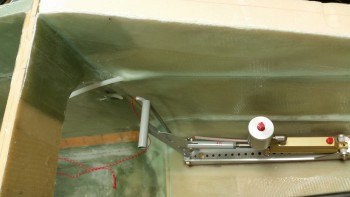
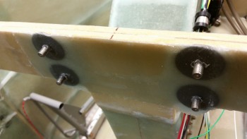
Later in the evening I pulled the peel ply and razor trimmed the voltage reg Click Bond mount layup as best I could with the razor knife. Tomorrow I’ll hit it with the Fein saw to clean up the lower edges of overhanging glass. I’ll also have to grind down about 0.1″ of each Click Bond overhanging the top & bottom edges of F22.
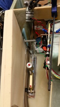
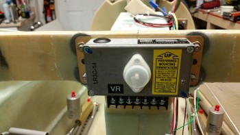
After cleaning up the mounting base a bit, I temporarily remounted the voltage reg to check the fit & appearance.
Tomorrow I plan on really glassing the right side nose panel in place.