
I started off today by knocking out the installation of Tee nuts into the mounting plate of my battery contactor. I don’t usually ascribe to using Tee nuts as a common practice in my airplane building project, but since these bolts are metric M5 bolts, and furthermore. since I found these stainless steel Tee nuts at that Mom & Pop hardware store the other day, I said what the heck… let’s do something the really EZ way for once!
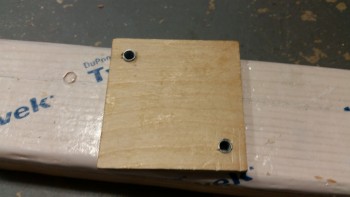
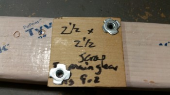
Obviously I used this scrap piece of Finnish Birch plywood when I was glassing the tabs for my main landing gear. It’s still good, so I’m putting it to use. I will be cutting the corners opposite the Tee nuts off at an angle to save some weight though.
I guess when my building compadres accuse me of cutting corners during this build, they’re right!! haha!
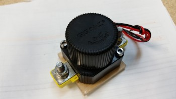
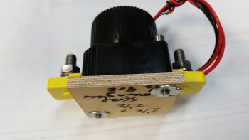
Here’s a couple shots of the battery contactor mounted to its new base plate.
With my 5 minute battery contactor base drilling task completed, I then moved on to working on the nose side walls. The first order of business today was to make the 2 triangular, angled foam wedges, one for each corner, that not only fills the small open gap that is created by the position of the side wall panels, but also provides some thickness to that area so that there’s actually foam (vs. air, as in a hole!) when the outer sides of the foam is sanded to shape.
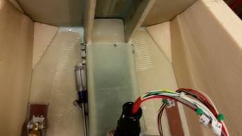
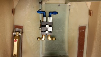
I then mocked up my parking brake to get an idea of how my brake components will be mounted in the nose area. As an aside, I’ve nailed down my brake line configuration so that I now know every item from A-to-Z on my brake system, including every piece, type & thickness of tubing down to every fitting. I’ll go more into that later in another post.
Also, note the 2 nutplate assemblies, one each just aft of the foam wedges. Each nutplate will allow the AN111-3 rudder cable bushing to be secured forward of the rudder pedal assembly as per the Rudder Pedal Installation Instructions (with the rudder pedal cable mounted to these bushing hard points it allows the rudder pedals to be moved without disconnecting the rudder cable, or having the hassle of reworking the length of the rudder cable when the rudder pedal is adjusted).
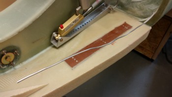
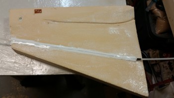
Today I’m actually going to follow the Davenport Plans and install the 1/4″ Nylaflow Pitot Tube by burying it in the left nose sidewall. Well, bury may be a bit severe of a word, since I’ll merely route out a 1/4″ channel and run it in that.
The pitot tube height is based off the center of the next-to-be-mounted-bulkhead, F-7.75, so I mocked that up for a few minutes (not shown) to get the approximate center and then went 90° straight out from that center point. I then drilled a small pilot hole on the outboard side of Napster that hit just the inboard edge of the nose sidewall foam, just aft of where I was drilling & on aft side of the F1-3 (Napster) bulkhead..
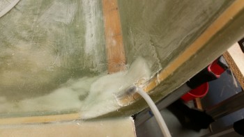
I then cut some of the fiberglass out that I had laid up a few weeks ago to protect the brake line that was exposed at the bottom corner edge of F22. Well, I needed it to be just a couple inches lower at the brake line tube bend, so a few minutes cutting its glass sheath away and I had the angle that I wanted.
I’ll also be burying a good portion of this brake line in the Nose side wall as well, so I’ll be adding more Nylaflow as a protective cover over this brake line tubing.
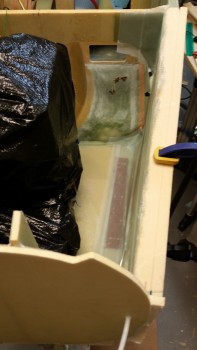
Here’s a shot of the brake line at the F22 junction, and how I cut the glass out so I could get the line at the correct height and angle for embedding it into the left nose sidewall.
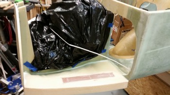
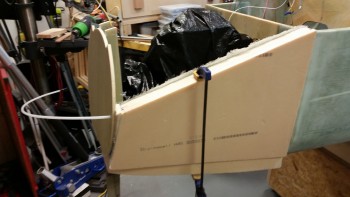
I then wrapped the NG30 nose box & cover with a plastic trash bag to keep any errant nasty stuff away from it.
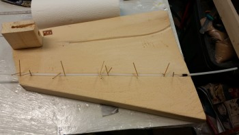
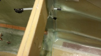
It was then time to start on the nose. I 5-min glued the pitot tube into its channel in 4 spots, and held it in place with toothpicks & nails. I also 5-min glued one of my new best friends, the lowly RivNut, into place at the forward end of the nose side piece. The RivNut is in line with the brake line and will secure it forward of the bulkhead mount that I’ll install later.
I then micro’d in both the pitot tube, and the rudder pedal cable nutplate assembly.
I then micro slurried the entire face of the left nose side panel.
I laid up the first of 3 plies of BID, keeping the edge glass and the glass just above the channel for the brake line dry. I didn’t want it wet and pulling apart as I micro’d the brake line in place.
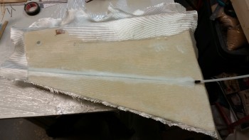
This was a tough, multi-faceted layup with a lot of moving parts. Too many parts actually between dealing with embedding the pitot tube & the brake line, ensuring there was the correct 3-ply overlap onto the already embedded rudder pedal base, etc. It got a bit frantic and hectic at times, and of course the physical work area is extremely limited.
Here’s a shot of the rudder pedal base, which now has 5 plies of BID on it so it’s pretty much officially installed.
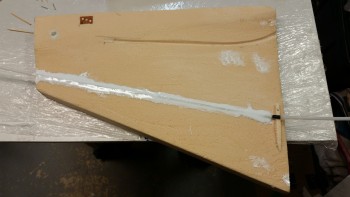
Another shot of the left side nose panel layup. Note the upper run is the pitot tube and the lower embedded run is the brake line, which comes into the nose all the way from the hellhole.
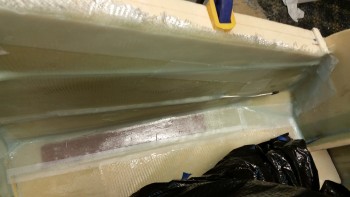
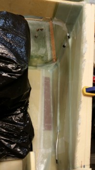
Here’s another shot of the embedded pitot tube and also the 3-ply BID layup in the top corner. This BID is reinforcement for the canard mount.
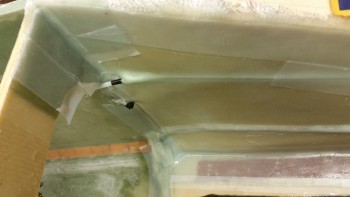
I glassed in the pitot tube with about a 6″ pigtail into the what will be the avionics bay (i.e. the space behind the panel whilst one is sitting in the plane).
And here’s one more shot of the glassed left nose sidewall! I may glass the other one like my buddy Marco did… which is glassing the entire side on the bench first and letting it cure, then installing it into the airframe with 2″ BID tapes. Some may call that lazy, but I call it smart . . . haha! (I jest my friend!). We’ll see.
Tomorrow I’ll clean up this install and check the quality of the layup. My plan is to then install the right side nose side wall.