
At least that’s what I felt like this evening . . . (and don’t ask me what it is, just focus on the prefix: “slog” … ha!)
I had meetings and appointments today so I didn’t get back to work on the project until after 1700.
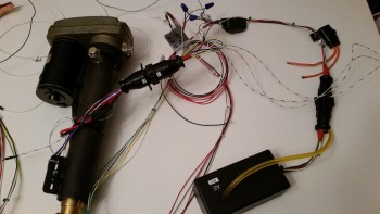
The first thing I did was to test out my new wiring connectors on the nose gear actuator. I double checked the connections, checked the battery voltage (12.86V) and then hit the switch. Ah, the motor came alive and down it went. Good deal. Then came the inevitable gotcha. I threw the switch the other direction to raise the actuator arm and heard . . . nothing. I double checked my wire connections, A → B, C → D, n → ∞, and all looked good.
So I tried it again. Nothing.
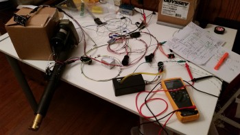
What ensued was about a 4 hour troubleshooting session where I did continuity checks on every single wire connection point, every run from starting terminal, through connectors, to the end connector and everything toned out perfectly on the Fluke. I checked the internal contacts from the P2 connector to the internal contacts on the AEX board. All good. I recharged the battery while I went out to the grocery store: fully charged at 13.23V, and still no up travel.
I reread Jack’s directions and happened upon a point of note about damaged microswitches. Since I now had extra I figured it wouldn’t hurt. When I started removing the microswitch on the right side facing the front of the unit, after marking its location of course, it literally crumbled in my hand. Not sure why that happened, but I replaced it. The good news is that I was able to reuse the lever arm from the newly deceased switch on the first switch body that got sucked into the ‘actuator of destruction’ and lost its lever arm. So I’m still down only one micro switch, but unfortunately the switch replacement still had no affect on the actuator being able to return to the up position.
Having exhausted every troubleshooting technique, and checking, double-checking and triple-checking every connection and continuity of wiring, I figured it was time to punt.
I’ll call Jack tomorrow to figure this thing out.
I took a break in the middle of the nose gear actuator troubleshooting saga above & spent about 15 minutes cleaning up the peel ply snots and edges of the right floor pan layup. Now both floor pans are ready for next steps.
Later in the evening, and I do mean late, with a fair amount of frustration with the nose gear actuator, and weary of chasing electron phantoms and wire ghosts, I decided to roll up my sleeves and at least get something glassed and curing so the night wasn’t wasted.
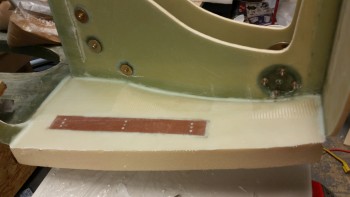
I turned my sites on the backside of the F4.1 (old F6) mini upright bulkhead that gets mounted to the aft side of the NG30 uprights. Although I keep wanting to write “aft,” I say “backside” because the side I’m glassing is not visible once glassed but actually faces forward. The F4.1 gets a 2-ply BID layup, and I’ll be adding two approximately 1″ wide strips on top and bottom as reinforcements for the velcro slots that will be used to mount the Radenna SkyRadar-DX ADS-B IN receiver.
Also on the list are the BC1’s, which are really a continuation of the NG30s into the forward battery box area just foreword of the F1-3 bulkhead (Napster). Since I will be mounting a retractable heated pitot tube, I had to mount the battery in a very specific location. This means that securing the battery will not possible in the usual Long-EZ fashion of simply strapping it to the nearing bulkhead. In the original plans that was a big function of the F6 bulkhead, since the battery was located immediately aft of F6 and was merely strapped to it.
My battery, for lack of a better description, will be out in free space. To ensure it stays in place I’ll be using a 2″ wide military grade web strap with a metal clasp and about 6-8″ of Velcro that will wrap around the center of the battery, holding the battery to the BC1s. But how you say? I will have a metal tube that is mounted between the BC1s, right under the battery. Since the tubing is clearly strong enough to hold the battery in place, I just need to ensure that the BC1’s are strong enough. Thus, I’ll be adding a 5-ply BID pad to both the inboard and outboard side of each BC1. The outboard glass will never get disturbed once glassed, while the inboard sides will be drilled to the diameter of the metal tube along with the BC1. In addition, I’ll have a thinner version of this type strap running around the battery from side-to-side.
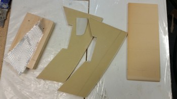
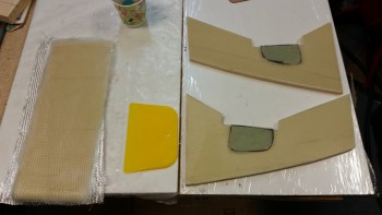
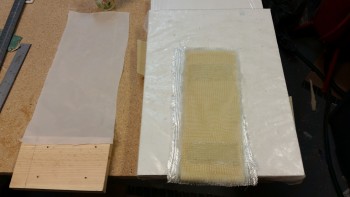
In preparation, I used some pulled peel ply from the floor pans to make up a small template for the 5-ply BID pads. I cut 10 small scrap pieces of BID and stacked them 2 plies deep in 5 stacks in a prepreg setup. I also cut 2 plies of BID for the backside F4.1 layup.
BTW, the 5-ply BID reinforcement pads are shaped the way they are to not only reinforce the battery mounting cross tube, but also to allow room for the center H100 foam piece that will get mounted in the channel between the BC1s, just below the 5-ply pads.
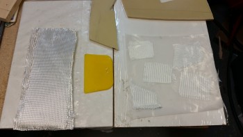
I mixed up some epoxy with slow hardener and wetted out the F4.1 layup and the prepreg BID.
As you can see, I continued to wet out the F4.1 layup while also using my template to mark up the 5 sets of BID for the reinforcement pad on the outboard BC1s. [Note: Since the F4.1 is H100 foam, I didn’t use micro to prep the surface since the foam is so tight grained it merely laughs at micro).
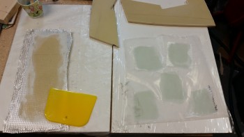
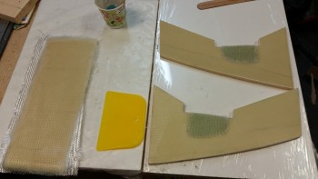
I cut out the 5 BID pads for the BC1s.
I continued to work the F4.1 layup making sure it was completely wetted out in-between the different steps on the BC1 BID. After applying a thin layer of epoxy on each layup area on the BC1s, I then laid up the BID pads one by one on the surface of the BC1s where the battery tie down tube will get mounted. I split the last 2-ply BID prepregged pad for the fifth and final ply on each BC1.
I then removed the final top piece of plastic on the 5-ply BID pads.
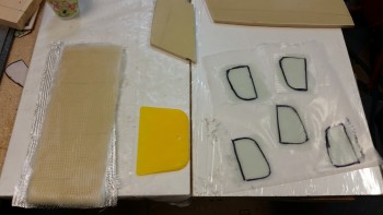
I added the approximately 1″ x 3″ reinforcement ply both top & bottom on the F4.1 and also peel plied the BC1 5-ply reinforcement pads. I applied the peel ply a little wet since the 5-ply BID pads are thick and I wanted a good smooth transition between the pads and the original surface of each BC1.
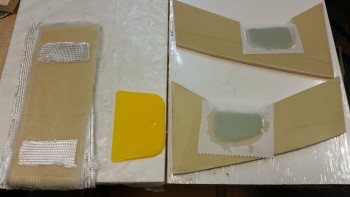
I finished wetting out the F4.1 reinforcement pads and covered the BC1 assemblies with plastic Saran wrap.
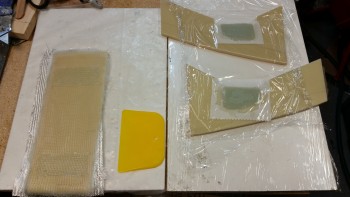
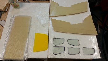
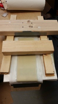
I then cut a piece of peel ply from my roll of peel ply and began to prep it for F4.1 by taping a 3/4″ block of wood to the end of it. This wood will serve as a weight to keep the glass conformed to the curved bottom end of the F4.1. [Note: The reason the bottom of my F4.1 plate is curved is because I rounded all the corners on my NG30s to minimize any potential stress points, and because I’m just damned fancy . . . haha!]
Note that I have the F4.1 work piece sitting atop the BC1 assemblies.
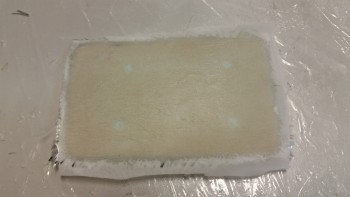
Below is the peel ply applied to the F4.1. I taped it on the top side with the weight pulling the glass over the curved surface on the opposite end (nearest the camera). The block of wood is not very heavy of course, but it is just enough to keep the glass conforming properly (read: “attached”) to the curved bottom end of F4.1.

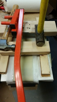
I then careful stacked some blocks of wood around the F4.1 layup.
And added a few heavy items to weigh down the 5-ply BID pads laid up on the BC1s. Now, I didn’t use something bulky like a gallon paint can to weigh this thing down because I wanted it open so I could aim a heat lamp at it without all my heat rays getting blocked.
Since I had a good little bit of epoxy left over, and I hate wasting epoxy, I grabbed some foam out of my scrap pile to make up a small 3″ wide by 6″ long 1/4″ thick “draft plate.” This plate will sit immediately above the NG6B nose gear pivot and will keep the cold draft air coming in to a minimum. My buddy Marco came up with the idea and since it’s a good one, I’m copying it! You can check out his version of this here.
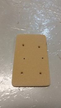
This is regular 1/4″ PVC foam, so I micro’d it with slurry and then filled in the holes with thick micro. I then laid up 2-plies of BID, and since it will be getting glassed into a very tight spot between the NG30s I peel plied it so that it I could have BID tape coverage anywhere I needed as I attach it.
Tomorrow I’ll call Jack Wilhelmson and figure out the issue with the nose gear actuator. I also plan on finishing the right side nose wall piece. However, I’m not going to glass in the nose side walls until I get some other tasks crossed off the list since I want to have easier access to the internal nose areas without two big side walls staring me in the face.