
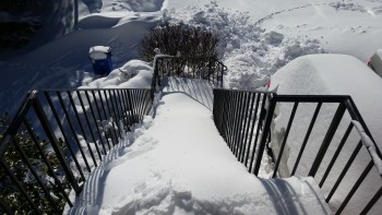
I wanted to start out this post showing you what I was dealing with yesterday. As I’m sure a lot of you know, the East Coast got hit with a big snow storm over the last couple of days. The final tally was well over 2 feet of snow, which made for a Sunday full of shoveling snow.
This is what greeted me when I opened the front door . . .
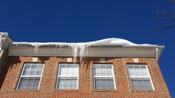
Even the “skies” threatened Daggers of Death!
So, combine dealing with the snow, watching two playoff football games & having my neighbor over for a few beers, I didn’t get any plane building done yesterday.
Today however, was all about getting the taxi light installed. I started by cutting away the nose glass that was covering the taxi light hinge channel with the Fein saw.
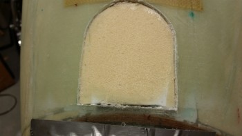
I then installed the taxi light hinge and dug out enough foam to swing it aft.
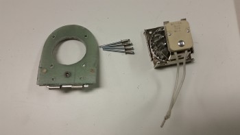
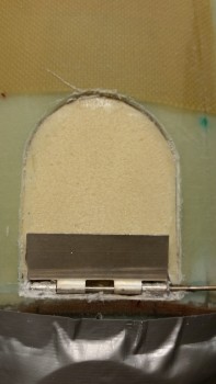 I got the hinge embedded in the foam deep enough that I could place the taxi light bracket/door back in place to mark up the drill point for the mounting screw. The mounting screw will go in the center of the hinge and will serve double duty to hold the torsion spring arm in place.
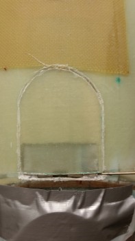
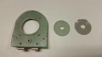
For the fiberglass taxi light mounting bracket & door, I marked up an 0.02″ thick aluminum sheet to cut out for a reinforcement backer piece.
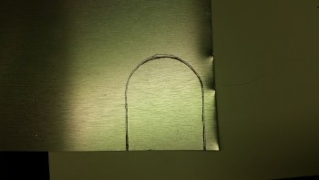
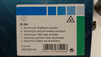
BTW, this is the anodized aluminum sheet that I bought in Germany as the nutplate reinforcement backer for the landing brake.
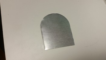
Here’s the cut anodized aluminum backer reinforcement plate for the taxi light glass swing down door & mounting bracket.
With the aluminum reinforcement backer plate cut out, I then clamped the bulb mounting bracket to drill the forward/top rivet holes.
Here are the rivet holes drilled.
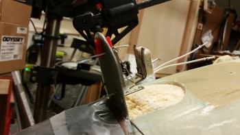
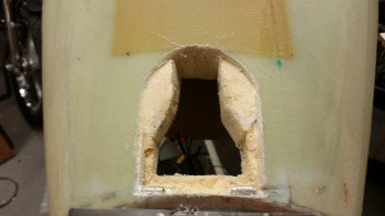
I then mocked everything up on the nose and slowly started cutting away foam to allow the light assembly to retract back into the nose as much as possible.
I finally got to the glass that makes up the battery compartment floor. I double checked under the glass to make sure I had clearance …
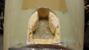
… and then cut out the glass to allow for full retraction of the taxi light assembly into the nose.
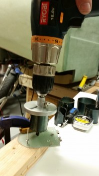
I then modified a hole drilling saw blade to keep the center guide drill bit off the lens. I figured if I put it in the drill press it might work.
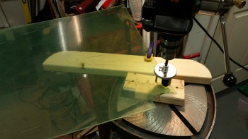
Uh . . . it didn’t. Big fail!
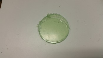
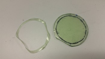
So I went back to the ‘stone age’ way of cutting out the taxi light lens. I first marked up an 1-3/4″ circle on the plexiglass.
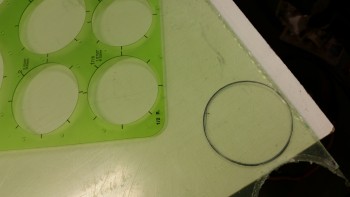
And then cut it out with the jig saw . . . See? Stone age! ha!
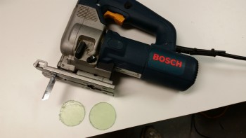
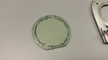
I then test fitted the lens on the taxi light. Looking good.
I reassembled the hole saw to cut a 1.5″ hole in the taxi light door/mount.
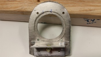
Here’s the lens hole in the taxi light door/mount.
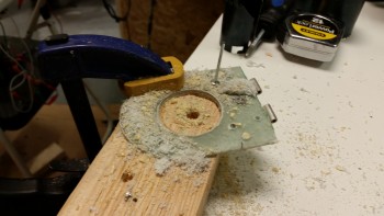
Another shot after I cleaned it up. I had to sand a little bit more out of the hole, but in the end I was happy with the size & shape of the lens hole.
I then marked up the size of the lens hole in the door/mount onto the protective plastic of the plexiglass. I then cut away the plastic around the edge of the lens with a razor blade and then roughed it up with 100 grit sandpaper.
I also sanded the edge of the aluminum reinforcement backer plate in prep for mounting the taxi light lens cover. I then put a very small bead of silicone RTV on the edge of the plexiglass lens and mounted it to the taxi light door/mount.
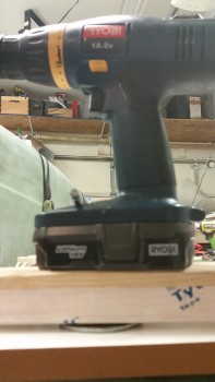
I put a block of wood on the taxi light lens cover and then weighed it down with a drill.
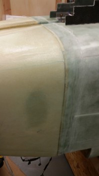
While the silicone RTV on the mounted lens cover cured, I knocked out another task on my Chapter 13 to-do list by sanding the junction between the recently glassed nose & the fuselage.
I also injected a half dozen small dime to quarter-sized delams (ugh!). You can see one of these delams right under the added glass patch on the right side of the nose.
After a good hour+ cure on the silicone RTV, I then set up to mount the taxi light bulb mounting bracket to the door/mount. Note that I already mounted the two lower outboard flush rivets.
Here’s a shot of the cured silicone RTV-mounted lens cover on the taxi light door/mount.
I inserted the Pop Cherry rivets into place in prep for mounting the bulb mounting bracket to the taxi light door/mount.
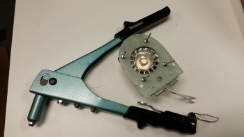
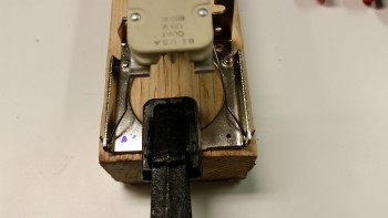
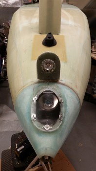
I then riveted the bulb mounting bracket to the taxi light door/mount. Here’s a shot below with the taxi light assembly in the retracted position. If the light assembly looks a little off center it’s because it is. The assembly sits 0.15″ to the left to allow space on the inside of the battery compartment for the extension hardware. In addition, there’s a very slight offset to the LED bulb bracket as well. In the end, although I would prefer that the taxi light be aligned dead on the CL, it is still completely functional so I’ll live with the slight offset.
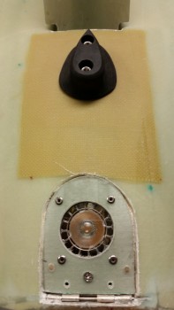
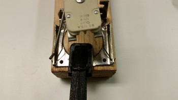
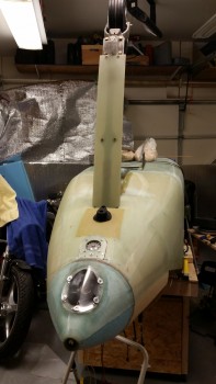
And here’s a couple of shots with the taxi light assembly in the down/extended position.
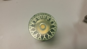
I then hooked up the taxi light to power & fire it up!
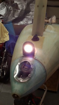
I then turned off the shop lights to check it out.
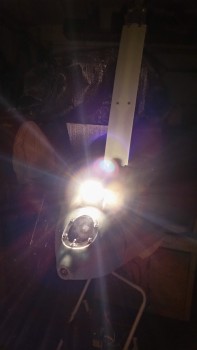
And here’s a shot of the light pattern on the wall. At 20° wide, the taxi light pattern is much more diffuse than the landing light’s 6° pattern, which is of course why this LED bulb makes such a great taxi light.
Of course I had to get a pic with both the taxi light and landing light fired up!
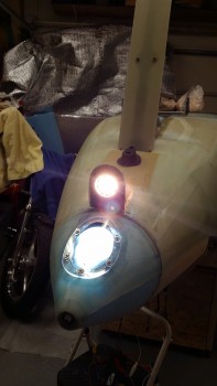
You can see the clear difference between the taxi & landing light beams on the wall, shown in the pic below. Obviously, there is a blue & yellow color difference, but the landing light is also a focused 6° beam angle aimed around 13° down that is optimized to light up the runway in the landing configuration of the Long-EZ on final approach. On the other hand, the taxi light is a more 20° broad beamed light aimed straight ahead when the aircraft is taxiing on the ground which is also optimized for its purpose of ground use.
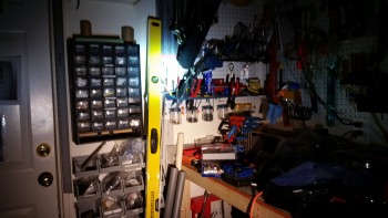
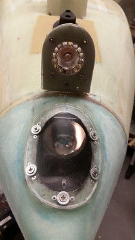
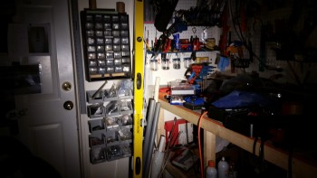
Here are a couple of shots with the taxi light in the retracted (“stowed”) position.
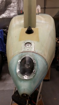
I’m going to leave the rest of the taxi light install for a later date. I need to put some more thought & R&D into exactly how the mechanism will work to get the light to extend & retract. As you know, I’m trying to link it to the nose gear extension/retraction, but that needs a lot more work & refinement as well. However, since the major installation of the taxi light is complete, I’m happy with leaving the final install actions for later.
With my schedule tomorrow it will most likely be a lighter build day, but at a minimum I want to get the canard work bench cleared off in prep for working on the canard and knocking out the final elevator install. For a good couple days or so I plan on focusing on the canard & elevators to get those finished, remounted on the wall & out of the way.