
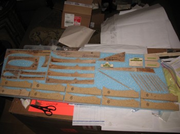
Today I started the build at the base wood hobby shop. I cut the remaining “L” templates for the Roncz canard, and cut outlines of the CS109 cockpit control system mount & RT3 Roll Trim bracket. Additionally, I cut 10 x 6″ dowels & 1 x 12″ dowel for the Roncz canard & sharpened them all to a good point using an old school pencil sharpener.
I used a coping saw to cut off the remainder of the 1/2″ x 1″ wedge-shaped angle on the front corner of the CS spar. I then sanded to shape the angle on the front corner to finish it.
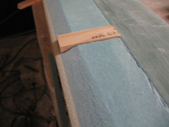
 I shaved just hair off the length of the top Spruce wood hard points so that they were just under 3″ in length.
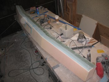
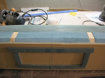
After I mocked up the Spruce hard points for a good trial fit on the spar top side, I flipped the CS spar and belt sanded the spar cap “steps” to smooth out the spar cap surface. I also hit the bottom spar cap with the orbital sander just to smooth it out a touch more. I then sanded the foam of the bottom side just in front of the spar cap to match the foam & spar cap to each other & smooth out the entire bottom spar surface.
I Dremeled all along the joint between the spar cap & the foam on both the top & bottom side of the spar, down the entire length of the spar caps to remove dead micro, flox, epoxy & glass.
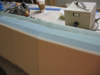
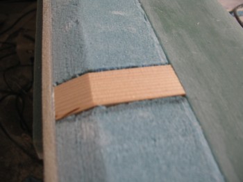
I made a trial fit of the Spruce hard points on the bottom side of the spar after marking, cutting out & removing the foam. I trimmed the bottom Spruce hard point blocks by almost 0.1″ in height to allow room for the micro that would be used to bond them in place. I then mitered the angle on the front of each Spruce hard point to match the angle on the spar face foam.
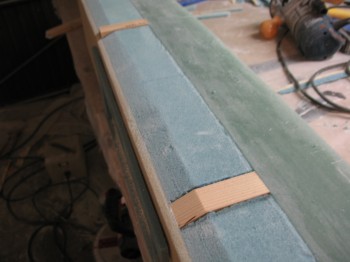
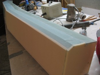
After all the prep was complete, I micro’d in the 2 bottom Spruce hard points.
I then cut the 4 layers of UNI for the final wrap of the top, bottom & back faces of the CS spar (layup #6). The front face of the spar is left to glass until last and accounts for the access hole in the front of the spar and also overlaps onto layup #6.