I started off today by making a decision on my electrical system, one that had been nagging me a bit in the back of my mind. The impetus for me making this decision today was a response by Bob Nuckolls on the Aeroelectric Connection forum that brought it all home for me. In a discussion on something else related to protecting wires with fuses and circuit breakers, Bob noted: “Recall that circuit protection is for WIRES . . . and that the protective device is installed as close as practical to the SOURCE of energy that puts the wire at risk.”
Thus, my ANL-40 fuse link is going back on the firewall, on the hell hole side. I’ll most likely use a piece of 1/8″ thick x 1/2″ wide copper to connect the forward (hell hole) stud of the Blue Sea terminal to one side of the ANL-40, then run the B-lead from the ANL-40 forward to the battery contactor (however, I’m leaving the option open to use 8 AWG cable and use this connection as the location for the GRT EIS Hall Effect sensor). This configuration will add a hair more weight aft, but puts better protection on the source of the B-Lead and cleans up my busy nose battery compartment a bit.
I didn’t mention conversations I had yesterday with both Rod Bower (RAM air unit) and Precision Airmotive (Silver Hawk fuel injection) as Marco and I were convoying in our separate trucks to his hangar. I asked the Silver Hawk guys if I could attempt to thread the -4 AN fitting on the top of the fuel injection servo as far as it would go into the unit in order to attain as much clearance as possible with the bottom of the cold air induction plenum situated just above the fitting. They said this would be no problem and that I wouldn’t damage anything internally/inside the fuel injection servo.
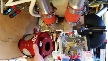
I queried Rod on some specifics about moving my RAM air box forward and mounting it directly to the aft side of the firewall, but he couldn’t picture it mentally and I ended up sending him the pic below much later after I arrived back home.
Rod got back to me today and we discussed mounting his RAM air unit with the nose of it sticking into the firewall, with about a 5.5″ gap between it and the front face of the fuel injection servo intake plate. The requirement for this gap between the RAM air canister –which would normally mount to the front of the fuel injection servo– is twofold: 1) The RAM air canister is too wide at the aft side of it (note that it’s shaped somewhat like an Apollo capsule) and would interfere with the bottom cowling. 2) There would be no clearance for neither the oil drain valve (brass valve in pic below) nor the forward-placed sniffle valve.
To allow for enough clearance with the aft end of the RAM air canister with both the oil sump above it and the lower cowling below, I determined that it must be mounted in the clear space just forward of the oil sump. This spot will allow the RAM air canister to be mounted an inch or so higher and still clear all the top side oil sump/cold air induction plenum and the lower cowling below . . . barely!
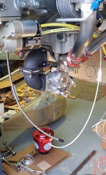
[In the pic below you can see the location of my initial planned hole for a 3″ bracket (shown bottom left corner), then a piece of 3″ SCEET tubing, then the RAM air canister mounted to front face of the fuel injection servo. Clearly, the reality of limited space and conflicting requirements for use of that space significantly changed the configuration of my air induction system. Currently the plan is to install the nose of the RAM air canister approximately 1″ higher than the circle depicted on the firewall below].
After some discussion Rod was able to see what I was talking about and signed off on the plan. In response to my question, he stated that he saw no ill affects in his assessment of my running a 2.5″ piece of SCEET tubing from the aft side of the RAM air canister to the front intake of the fuel injection servo (note smaller diameter than that previously planned 3″ SCEET tubing preceding the RAM air canister).
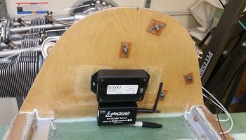
After getting Rod’s sign-off on the new air induction configuration, I then got busy mounting the Electroair MAP sensor unit on the front face of the firewall in what will be the GIB headrest/D-Deck component housing.
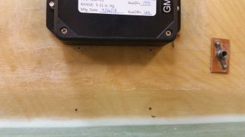
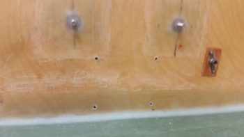
I marked the holes and here you can see the top 2 holes are drilled.
I then had to make some minor adjustments for hole alignment as I drilled the remaining 2 holes.
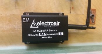
I then test fitted the MAP sensor, but will hold off on the actual screw install since I don’t have good access with the engine installed to the aft side of the firewall (the screws will get floxed in from the aft side of the firewall to the front side to create 4 screw posts… analogous to click bonds).
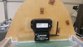
And another shot of the final placement of the GRT and Electroair MAP sensor units.
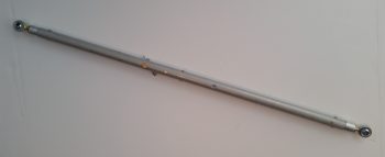
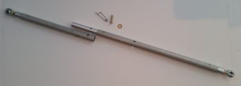
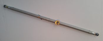
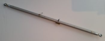
I then got busy assembling the new 5/8″ elevator control rod that would replace the old one that I so haphazardly decided to drill an extra hole into. I used some larger rivets that Chris Seats gave me and got busy drilling and mashing rivets! Here’s the assembled product.
Here you can see the internal rod that Marco lathed down the diameter of and cut to length. We of course cut the 2 main tubing pieces to length as well. Since I have so much real estate on the top end of the quick disconnect internal solid rod, I’m going to drill an extra #10 hole and actually install an AN3 bolt and nut in addition to the clevis pin.
Here’s a shot with the Atkinson pitch trim actuator bolt slid into the bolt hole that I drilled on this new 5/8″ elevator control rod. Again, the internal solid rod that makes up the quick disconnect also extends down beyond the pitch trim actuator bolt hole so the hole is much more robust than on the previous elevator control rod.
And here’s a view of the other side of the pitch trim actuator connecting bolt.
Tomorrow I’ll continue to finish up engine-related tasks and will specifically focus on the final placement and configuration of the air induction components.

