
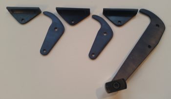
I started off today discussing a variety of issues via email with my buddy Dave Berenholtz, one of which was parts availability for the canopy latch system. I took the pic below of my Wilhelmson RL-1 rotary canopy latch components to add some clarity to my email and thought I’d include it here.
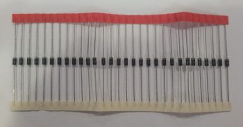
I also thought this string of 1N4007G Diodes that I just got in from Mouser would also make a cool pic and show you guys what they look like in “raw” form.
Here’s one of those diodes in action on one of the pigtails I added to 5 of the 9 panel On/Off indicator lights that allows me to tie into switch #4, the Push-to-Test button’s wiring harness. As I mention in the video (below) that I made to highlight the Push-to-Test button (and freshly wired dimmer) for these lights, I can only hook up 5 of the 9 lights to switch #4 for testing because the other 4 On/Off indicator lights contain closed systems…. where the configuration of the components that those lights report on do not support connecting them to the Push-to-Test circuitry.
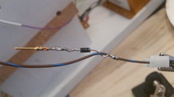
The added wire –in the form of a pigtail at first– to each light is nothing more than an alternate power source that provides 12V+ input to each indicator light connected to the Push-to-Test (PTT) circuit. The power provided by depressing the PTT button (switch #4) then flows to ground out of the other terminal of the light’s connector (via the dimmer switch).
Thus, I’m utilizing the diodes in the PTT circuitry (pigtails) on these lights as a one-way valve, preventing power being inadvertently applied to the other lights when only one has a real valid condition to cause the light to illuminate. For example, due to the way I’ve constructed the switch #4 wiring harness, if I didn’t employ diodes on each line then when I pulled the parking brake handle, which closes a switch allowing 12V+ power to run to the indicator light, the power would then back-channel through the pigtail (switch #4 wiring harness) and power up the other connected indicator lights. Obviously that would not be good, and as you can see these diodes prevent that scenario from happening.
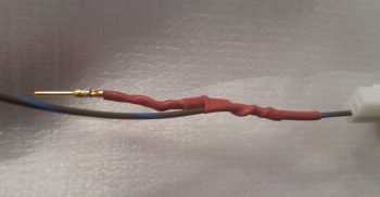
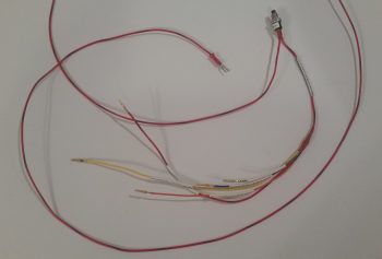
Here is the same pigtail as above only covered with red (for indicator 12V+ power) heat shrink. One thing I should point out is that the connection to these panel On/Off indicator lights for the Push-to-Test circuits utilize D-Sub pins and sockets that themselves will be secured with heat shrink. I used D-Sub pins and sockets due to the fact over a myriad of configuration changes on the wiring system, I have spare wires terminated with these pins and sockets. In addition, I have a good number of spare terminated 22 AWG wires of different colors (shown on the switch #4 side of the equation in its mini wiring harness) from included GRT and TCW wiring harnesses.
Just as I did on the panel On/Off indicator lights dimmer switch, I then determined the required wire lengths to the 5 lights that will be connected to switch #4 for the Push-to-Test circuit. I stripped the ends of these 5 wires of varying lengths and then soldered them all to the lead hanging off one side of switch #4 (the Push-to-Test button). The lead on the other side of switch #4 goes to 12V+ main bus power and since I didn’t know exactly how long this wire needs to be, I just terminated it with a cheap automotive connector for now. I then labeled the 5 terminated leads (4 pins/1socket) on this harness (I labeled the switch pigtail lead before soldering the harness together).
With my Push-to-Test switch & wiring harness complete, I hooked it up and tested it out. I was quite pleased at how both the dimmer and the Push-to-Test functions were working. So pleased in fact, that I decided to make a video, especially since it’s difficult to describe light dimming action, so I figured a video would help show it much better. I also briefly touch upon the new Engine function display page on the Mini-X that I just recently loaded.
As I keep saying, with the weather as cold as it is, which prevents composite work in the shop, I am focusing on getting a bunch of these small electrical taskers –mainly panel related– knocked out.