
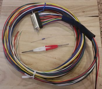
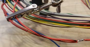
I started out today gathering up my GRT EIS4000 wiring harness, a 300 Ohm 1/4w resistor, and my D-Sub socket removal tool. My task here was to add a cross connect wire from the EIS4000’s blue 4.8V excitation wire to the engines oil pressure sensor’s EIS signal input lead. This is required to ensure the ~5V signal strength is maintained at the oil pressure’s input port on the EIS unit. Physically, it is simply a cross-connect wire from the blue to the orange/black wire in the EIS4000’s wiring harness.
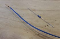
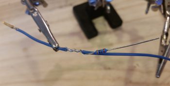
I started off by removing the blue wire from the D-Sub connector, then trimmed about a 1/4″ of the insulation off of it a few inches from the D-Sub socket and then wrapped one of the resistor legs around the exposed wire segment.
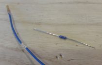
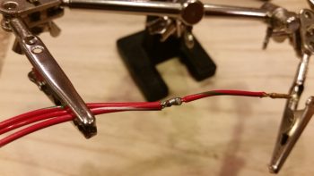
I then soldered the resistor to the exposed wire segment on the blue 4.8V wire. Next, I soldered a short length of 22 AWG orange/black cross-connect wire to the other leg of the resistor.
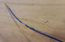
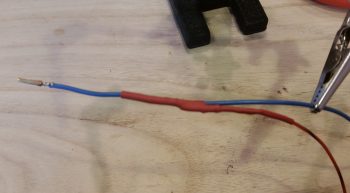
I then trimmed up any protruding sharp edges and enshrined my work in red heat shrink.
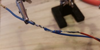
On the EIS4000 oil pressure sensor port’s orange/black lead I then exposed about a 1/4″ of bare wire just as I had done on the blue wire above, only this time it was 4-5″ downstream of where I had tapped into the blue wire. I then wrapped the stripped end of the cross-connect wire around the bare part of the oil pressure sensor wire….
and soldered the cross-connect wire to the oil pressure sensor wire.
I finished off my task with another round of red heat shrink over the cross-connect/oil pressure sensor wire solder-spliced junction.
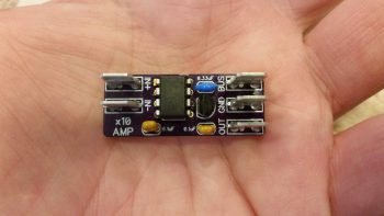
In other news… I finally received my Bob Nuckolls recommended and Eric Page built AD626 Op Amp board (for displaying Electroair Spark Advance on the EFIS via the EIS). Once again Eric did a phenomenal job constructing this board. I really like his concept of using PIDG FastON tabs for connecting wires to the board…. nice & EZ! Moreover, I’m extremely thankful that we homebuilders have a corroborative means such as the AEC forum to figure this stuff out. Such an excellent resource.
Although I won’t have any wire labels until Monday, thus keeping me from completely wiring up the AD626 Op Amp Board, I did start prepping the EIS wiring harness with connective wires to connect to this rather diminutive component. As an aside, the FT-60 fuel flow connects to a 12V+ port on the EIS4000. In addition, the manual specifically states to use this 12V+ port to connect the Fuel Pressure sensor. Thus, since I have 12V power at the ready (the AD626 Op Amp board uses very little power), I am merely going to tap into the EIS4000’s 12V+ port to drive the AD626 Op Amp as well.
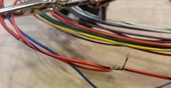
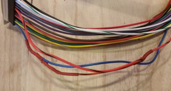
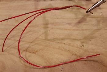
Pictured below are 2 wires connected to the bared 1/4″ section (just like above) of the EIS4000’s 12V+ out power port, making 3 out leads from this one port. The longer original Red/Blue lead is for the FT-60 Red Cube Fuel Flow Transducer. The next longer Red/White lead is for the AD626 Op Amp board, while the shortest red lead is for the Fuel Pressure sensor lead.

I then soldered the 2 added power wires to the EIS4000’s 12V+ out lead.
And then added some heat shrink to the solder joint.
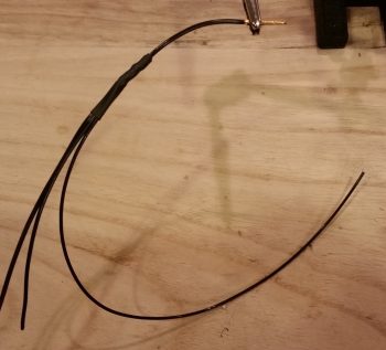
I pretty much did the same thing as above for the ground side of the circuit by tying into the EIS4000’s ground wire.
Besides my usual antics of updating associated wiring diagrams, and sending out some email inquires with a little bit of research sprinkled in, I was also able to finish editing a video that I recorded for my buddy Dave Berenholtz. The video discusses some topics on aircraft electrical wiring.
Again, with cold weather at hand I’ll continue in my electrical-centric mode until it starts getting a bit warmer.