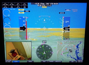
Last night at some point I was thinking about the actual physical wiring of the aft two cameras that each focus on a fuel site gage. I knew that before I could finalize my decision that I would have to test and verify that 24 AWG wire would provide enough juice for the cameras to send a good video signal.
What was gnawing at me was an issue of consolidation, and one of cable management. Dealing with 3 separate 24 AWG wires isn’t an insurmountable task, but I thought there might be some efficiencies to be had. I drifted to sleep with this on my mind.
Then there was the question I had this morning regarding those pesky LED lights on the fuel site gauges themselves. Hmmm, how will the wiring on these critters actually physically get run?
Then I had an idea. An idea that has eluded me for almost 7 years, considering Vance Atkinson’s fuel site gages are the first components I purchased, IIRC, for my Long-EZ project: What if I inverted them and put the LED on top? I pulled the installation instructions out to find, lo and behold, that the last line on the page –hand written– said that I could mount the LED on top OR bottom. Cool!
With that info in hand, I then planned initially –to be verified with some camera tests– to use a 5x24AWG conductor wire to handle both my aft camera and fuel site gage wire runs. Each aft camera would use 3 of these wires while each fuel site gage would use the remaining 2 wires…. again, all 24 AWG wires packaged nicely in one cable.
Since I don’t have any wire label stock on hand (they should arrive tomorrow) the first thing I did today was something else I haven’t done in almost 7 years, I tested the “red” LEDs (as listed on the included specs & install sheet) on the fuel site gages to find out that they A) worked, and B) are in fact actually white LEDs, not red.
I then took about 45 minutes to get some low hanging and long overdue bits ordered. I finally found and ordered a couple of pieces of 1.5″ diameter heat shrink off of Ebay (I checked McMaster-Carr, WAY too expensive) primarily to encase/protect my relay that controls COM1-COM2 radio flip from the control stick. I also ordered a length of a rubber automotive seal that I’ll use for mounting the GNS480 GPS antenna puck cover atop the pilot headrest (after 20 min the ONLY source of supply for what I wanted was again off of Ebay, and straight from China no less).
I then got to work on my wiring diagrams to upend the Atkinson fuel site gages and depict their new orientation correctly. I also better depicted their actual physical wire runs and added in the visible segment of the 5x24AWG conductor wire. I have two diagrams, fuel system and cockpit lighting, that contain the fuel site gages so I tweaked one of them to the new “final” configuration and then merely copied over the entire new depiction to the other diagram.
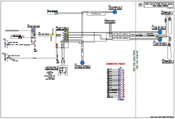
I then spent a few hours doing something I haven’t done in a fair while: I created a new wiring diagram for the Video Camera Network. Here is a saved JPG version of that diagram. I was putting the cart before the horse slightly in that I hadn’t tested out the 24AWG wires –at least the non-shielded wire version– for the video cameras, but I was quite confident that it would work.
After compiling all the data I needed to represent the Video Camera Network wiring on a system diagram, I then set about testing my 24 AWG hypothesis. Fortunately, I found about a 7 foot length of the exact 5-conductor wire I want to use for the aft cameras, so this would be a great representation to check the video display quality using near the same length of wire.
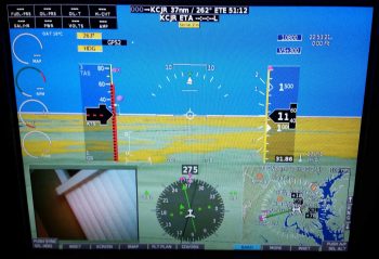
I then stripped off the first couple inches of the outer insulator and grabbed 3 of the wires to hook up to micro-video camera #1 for testing. I soldered the wires to the camera leads off the tiny PCB board that the camera uses for 12V-to-5V conversion, and then hooked up the camera at the EFIS side. I fired up the EFIS and as you can see in the lower left inset, I got a very readable video display from the camera.
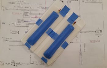
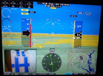
Since this camera is going to be used to view the fuel quantity in a fuel site gage, I amused myself (yes folks, constant electronics will drive you stir crazy!) by placing the still-wrapped site gages in the video camera’s view to snap the pic below.
I then spent a good 20 minutes desoldering a connector off a PCB board (I stole it off the defunct 5v GNS480 indicator light that burnt up) and then soldering three 22 AWG wire leads to it. I then connected my 5V “wide angle” video camera #3 up to the EFIS and 12v-to-5v converter to test it out. As you can see below, although not nearly as “wide angle” as I was expecting, the video display quality is fine.
Now, I noted that a few of my 5V components go from 5V+ power on the positive lead then simply hook up to standard 12V ground on the negative lead. Since these cameras depict and physically have a both a positive and negative side for the video signal (via the yellow RCA jack) and on the camera power input (via the red RCA-type jack) I figured each component needed a direct connection to ground. I noted this concept was supported in Eric and Alec’s design of my 4-into-1 video signal sequencer, since on the unit’s D-Sub connector they placed a signal ground pin right next to and for each video signal input pin. Moreover, also on the unit’s D-Sub connector they had a pin for camera power and another for camera ground. Ok, so that’s how it needed to be wired (allegedly).
But back to my 5V ground vs 12V ground, as I was testing the grounds on camera #3, I pulled the ground off the outer ring of the video signal RCA jack which resulted in ZERO impact to the video signal. It was still right there on the screen. In fact, I moved the camera just to ensure no weird screen capture event had occurred.
Hmmm, interesting.
Ok, so then I disconnected the ground path to the 12v-to-5v converter. The EFIS video inset screen went blank. I then tried re-hooking up the ground to the outer ring of the video signal RCA jack…. still no video signal. Reconnecting camera ground brought the video back live again.
So the 2-ground requirement I had noted in the camera install manual does not seem to apply, at least for seeing the video signal. I’ll have to double check in the manual to see if it keeps the unit from errant electrons or something. Moreover, I tested this on camera #1 by hooking it back up and found the exact same results: no ground lead required on the video signal RCA jack. Not a huge find in how it impacts the amount of wiring effort, since it merely eliminates 3 small ground lead pigtails… but it is nice to know.
I depicted this on my new Video Camera Network electrical diagram and with confirmation that the 5x24AWG conductor wire will work I then labeled all the wires with the appropriate wire colors.
Again, tomorrow I should be getting my wire label stock delivered so I can get back to finishing up some tasks that require wires to be labeled before next steps can be completed.

