
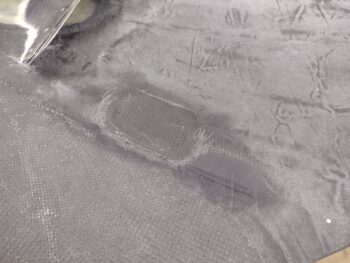
I started off today by removing the bottom cowling and finally pulling the peel ply and cleaning up the left inside bottom cowl exhaust pipe clearance depression CF layup. Now this task is officially done.
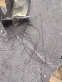
Before removing the bottom cowling I had outlined the right inboard exhaust pipe at the elbow, which is where a clearance issue still exists between this area of exhaust pipe and the bottom cowling. I have double and triple checked all the other exhaust pipe-to-bottom cowling clearances for all the pipes and the rest are good. This is the last bottom cowling clearance issue that I need to resolve.
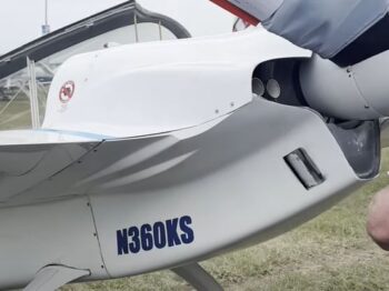
I’ve pondered over the last few days of how I was going to resolve this right aft/inboard exhaust pipe clearance issue with the bottom cowling, even considering cutting the pipe and angling it upward a bit, but finally decided to work the cowling vs the exhaust pipe. I’m gong to plagiarize here and copy Klaus Savier’s design for bottom cowling exhaust pipe clearance by creating a slash-type bumpout with a sharp angle along the edge… specifically along the lines of the inboard slash-type bumpout shown here.
With the bottom cowl off I determined what was a straight line for the sharper vertical edge of the clearance bump by going off the leading edge of the bottom cowl, which I assessed as near to exactly perpendicular with the aircraft centerline. After marking the outboard straight cut line on the inside of the cowling, I then drilled a tiny hole at each end of the line and pressed rivets into the holes. I then flipped the cowling over to draw a straight line between the rivets for my proposed external cut line.
I then temporarily remounted the bottom cowling to check my cut line to see if it was actually straight and parallel with the aircraft’s centerline. It looked fairly straight, but being on a curve it looked like it leaned out a bit.
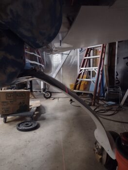
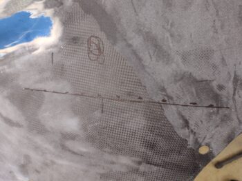
I set up the laser level and with the laser line hitting the two rivets I determine the laser level was 16.75″ away from the center of the prop hub (pic 1). I then placed a clamp sticking outboard at F22 and dropped a plumb bob at 16.75″ out from F22’s centerline. I then lined up the laser line by moving it a smidge so that it hit the two rivets and the far plumb line (pic 2). I then marked the straight laser line with dashes between the 2 rivets.
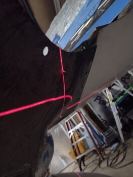
Fun with geometry! Although the starting and ending points (the rivets) are in the same spot, a straight line over this curve is just a hair off from my original “straight” line (the solid line).
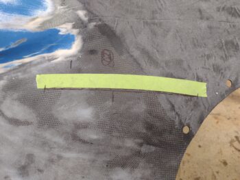
I started to use a piece of tape to mark the cut line, then just said ‘screw it’ and simply used the tape to cut the line. Now, before I cut out the clearance hole I used a multipoint shape tool to capture the curve to make a template of the outside vertical edge (“smile”) of the clearance bump/divot.
I’ll note that the house next door to me was owned by an elderly couple that very occasionally would come down to stay for short lengths. They sold it to some people who are now living in it full time, so I don’t want to make crazy loud noises now when it’s late at night. Since I needed to run to Home Depot, which is 45 minutes away, I wanted to get this loud cutting done so I wasn’t doing it later in the evening.
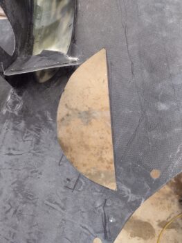
That all being said, here is the right side inboard exhaust pipe clearance cutout on the bottom cowling. Again, to mimic somewhat how Klaus has his bottom cowl exhaust pipe clearance bumps.
I then ran out to Home Depot in my quest for 1/16″ Plexiglas for the wing light lenses, which they had listed as in stock on their website. Well, it was in stock but it was made for picture frames and was somewhat translucent with objects only closeup being clear. I then ran to an arts and craft store and they only had 2mm (0.078″) thick acrylic in stock. No joy.
When I returned home later in the evening, I spent about an hour cutting out the clearance bump/divot’s outside vertical edge (“smile”) template from scrap cardboard and creating the other horizontal part of the mold as well… assessing how I was going to do this layup the whole while. I had planned on using the vertical cardboard template as part of a mold to layup the outside plies of CF first for this clearance bump/divot.
I then realized that the cardboard was too weak: not as a form, but in getting it as a free standing form to attach securely to the bottom cowling for the layup. It became clear rather quickly as I started my attempt to make a form on the bottom cowling that I needed to transfer the cardboard template to thin plywood. And it was way too late to start that, so I kicked that can down the road until tomorrow…
So I closed up shop, went inside and did some more research on cast vs extruded Plexiglas… and then spent a good bit of time looking for vendors that had that darn elusive 1/16″ acrylic/Plexiglas in stock!
Moreover, in case I don’t get a blog post in tomorrow: Happy Thanksgiving everyone!