In preparation for installing the aileron control components in each wing, I am reviewing and assessing how my fellow builders accomplished this task… mainly Dave Berenholtz and Ary Glantz, both very talented builders in their own right.
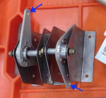
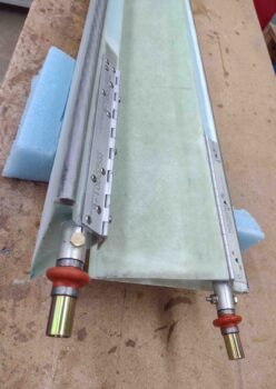
In reviewing Ary’s excellent write-up on his blog I came across an issue that was hiding in plain sight. I’ll start by stating emphatically that I love the Cozy Girrrls, Chrissi and Randi, and all they’ve done for this community. But I have to say in all honesty that I’m disappointed in the info I just unearthed on Ary’s write-up concerning the aileron control system CS128 Belcrank that they sell. As innocuous as it may seem, their belcrank comes with 1/4″ holes on each arm for attaching the control tube rod-ends. On the surface no big deal, but it’s definitely causing me headaches in time, money and effort . . . read on.
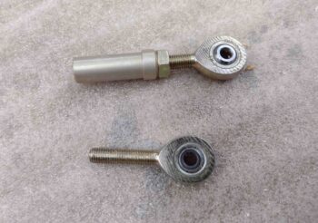
Without doubt using 1/4″ holes here is in line with the plans changes in CP 102 and CP 103 to increase the size of the rod ends from 3/16″ to 1/4″, at least on the face of it. And maybe using 1/4″ rod ends is a standard in the Cozy world. However, after this mod hit the streets and Long-EZ builders, fliers, and/or owners were tasked with converting their rod ends, Rick Girard, Ken Miller and others discovered a little gem sold at Wick’s Aircraft: the XM-3. In Rick’s words:
“First thing is, do not use HM-4’s. Wick’s has a rod end that has a 3/16″ hole in the ball and is in every other way equivalent to the HM-4. This will save having to drill out all the bell cranks. Wick’s part number is XM-3 (I know it doesn’t make sense unless the dash number spec’s the hole in the ball, but it is a 1/4-28 thread).” Read here, page 22.
I followed suit and bought 8 of the XM-3 rod ends for the aileron control system.
And now I’m following suit after reading Ary’s blog and buying four Heim HM-4 rod ends in a scramble to get the aileron control system installed. To be fair, the CS128 listed on the CG site does state it uses MM-4 rod ends, but it would have seriously made life way easier for a number of builders if these were produced with 3/16″ holes to then allow HM-4/MM-4 users to simply take a minute to drill them out to 1/4″.
I’ll know and assess more when I get the 1/4″ rod ends in hand, but looking at Ary’s write-up the kicker isn’t really even the requirement or cost to get these new rod ends: it’s the resulting lack of clearance with them installed. Ary stated that he had to rewicker the configuration of the Belcrank in the CS127 brackets by trimming down the CS131 spacer and adding washers below the Belcrank to reposition it higher simply to add clearance for the bigger AN4 bolt heads. Now we’re getting into make-work on a supposed off-the-shelf part… which is quite frustrating to a project manager like myself.
I thus fired off an order to Aircraft Spruce for these new rod ends and a few other parts.
Moving on.
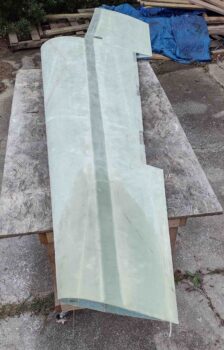
I’d say I took my frustration out by sanding the top of the left wing in prep for micro finishing it, but let’s be honest: sanding sucks. As on the right wing, I spent about 2 hours getting a good dull finish on the top surface of the left wing. The good news is that I plan to follow Wayne Hick’s lead and peel ply the top strakes when I glass them, which only leaves the winglets as any major area to sand remaining… as far as fiberglass. Obviously lots of micro-sanding left in my future!
After a bit more research, confirming task sequences, etc. I dove into the initial steps of installing the aileron control system components. Again, pulling from other builders (a shout out again to both Ary and Dave), my overall plan falls in line with Wayne Hicks specific suggestion to start from the aileron itself and install inward towards the firewall (which is fairly in line with the plans method as well).
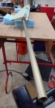
I first positioned, drilled and bolted a MS20271 B10 Universal Joint into the A10 tube on each aileron.
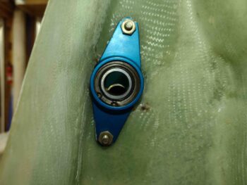
Over on the actual wings I mounted the wing root bearings then slid the CS152 tube with the CS132 weldment bolted to it into each bearing.
I then took the CS151 aileron torque tubes and slid them into place over the CS152 tube and pressed up against the internal face of the wing root bearing.
I then made a mark on each CS151 even with the inboard edge of the wing aileron pocket.
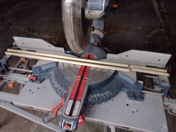
With that, I subtracted the distance of the aileron A10 nub and (now) added U-joint, which is 1.9″. I also needed to remove another 1/4″ for the space identified in the plans that needs to be between the end of the CS151 tube and the wing root bearing face. With my measurements calculated and marked, I then trimmed both CS151 aileron torque tubes to length.
And then temporarily mounted the CS151 torque tubes to the inboard nub of the Universal Joint using electrical tape.
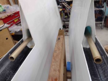
I then carefully mounted the ailerons onto the wings with the CS151 torque tubes temporarily attached.
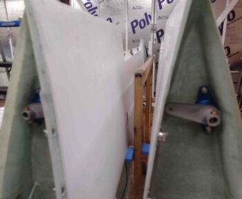
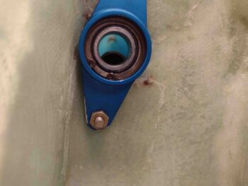
I removed the CS152/CS132 setups out of the wing root bearings to allow me to see the end of the CS151 aileron torque tube inside the bearing center hole.
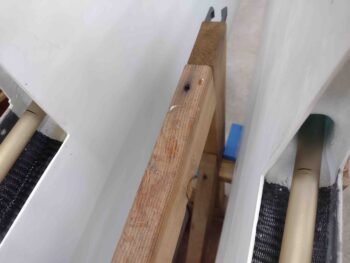
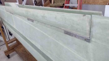
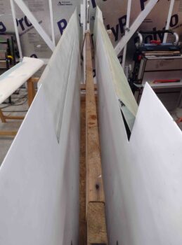
Here we have a view of the CS151 aileron torque tube inside the hot wired inboard wing channel.
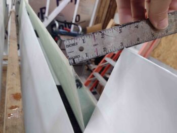
I measured the gap between the inboard edge of the CS151 aileron torque tube and outboard face of the wing root bearing on each wing. On the right side I’m right about at a 1/4″ gap, while on the left it’s a little shy at 0.214″… so I’ll shave just hair more off the left CS151.
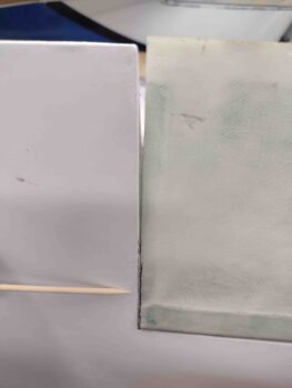
I also noted another issue when remounting the ailerons for the first time after having laid down primer and paint on the bottom surface of the wings: my gaps between the inboard aileron edge and wing aileron notch is essentially AWOL on the forward side of the aileron.
On the right wing you can see it needs some cleaning up to regain the nice gap I had… at this point the aileron is pretty much locked into place as far as any movement.
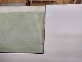
Over on the left wing I removed the aileron and trimmed the inboard edge to allow freedom of movement, although it started out looking pretty much like the right aileron did above. It was getting quite late so with the left good I decided I’ll fix the right aileron tomorrow.
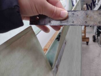
I will note that I’m happy with the initial aileron swing of 3″ each direction, showing that even with the CS151 torque tube installed that the opening of the inboard aileron pocket is plenty large enough to allow for freedom of movement. How this plays out once all the components are connected up remains to be seen!
And with a long day under my belt I called it good and headed in for a late dinner.
