
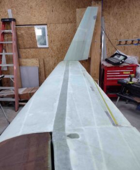
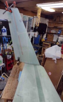
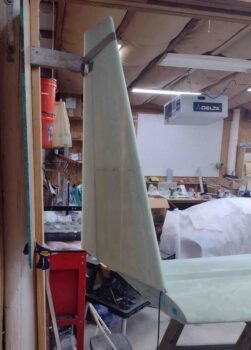
I started out today with placing the winglets on the end of each wing to create jigs to both support the winglets upright and also allow me dial in the A, B, and C dimensions as per the Chapter 20 plans.
I started on the right side setting the winglet in place to then constructed a temporary jig assembly outboard of it using the center sidewall pillar in the shop.
Note the decimal tape measure locked into the corner of inboard aileron at WPRP. I had bought some long aluminum channel to use to get repeatable measurements, but for me it was clunky and a pain to manage, and frankly by pulling the tape measure really taut, I’m confident that I’m meeting the plans “within 0.05 inches” tolerance on my A, B, C dimensions.
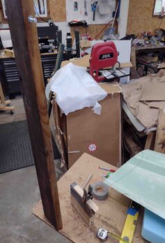
On the right side I screwed a temporary backer board into place onto the center shop pillar that allowed me to attach a clamp on the bottom to support the aft bottom edge of the winglet, as well as cut an angled 2×4 nearly a foot long to support the top outboard side of the winglet. I simply kept the winglet in place on the top with duct tape.
Once I confirmed that the winglet was in a good general position with the relation to the top 2×4, I then removed the winglet and the 2×4. I say ‘general position’ since the C dimension between WPRP and very top aft corner of the winglet here is over 120″ where per plans it needs to be 118.35″. Clearly the winglet top needs to tilt inboard a bit more, and I accounted for that below.
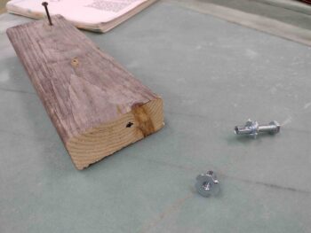
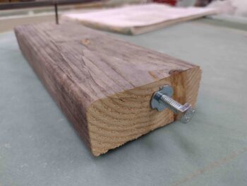
I drilled a hole in the end of my 2×4 winglet support arm and inserted a tap-in threaded standoff. Clearly by adjusting the 1/4″ bolt I can dial in the C dimension quite easily (more pics on this installed later, below).
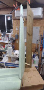
I then got to work on setting the winglet jigs up for the left winglet. This setup is quite a bit different since I have no nearby wall or post to work with, just a work table below the end of the wing (almost as if by design… wink!).
I stacked two 2x4s on edge and screwed them in place as the support for the aft bottom of the winglet. For the outboard top I screwed a scrap piece of long 2×6 to the table as close to the outboard edge of the winglet as I could get.
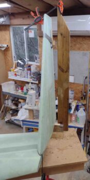
I drilled and installed a threaded standoff on the edge of the 2×6 as I did on the right side. I’ll note that the inboard lean of the winglets to obtain the 118.35″ C dimension required an extra wood spacer or two on each winglet since my standoff bolts were a bit short to do the job all by themselves… a minor inconvenience.
Here’s the left wing trial setup of the winglet mounting jigs and spacers.
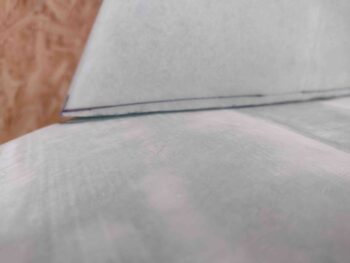
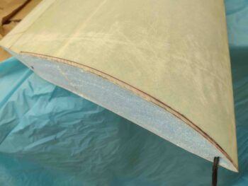
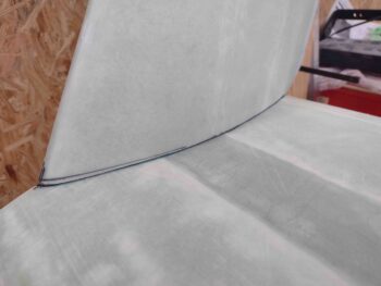
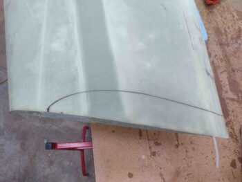
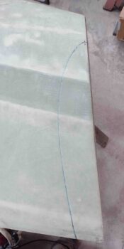
I discovered a very significant issue on both winglets as I was dialing in the A, B and C dimensions… something was afoot with my bottom winglet trim job. I had followed both the template I had and the plans, but the curve at the very front of the winglet wasn’t sufficient to follow the curve of the top of the wing. I had a good 0.2″ or so gap at the very front bottom leading edge of each winglet and the wing top.
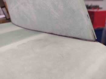
I still set the A, B and C dimensions to ensure I was as close as possible to where I should be with the winglets in place, then laid a fine-tipped Sharpie flat on each wing and marked a contour line onto the bottom inboard edge of each winglet.
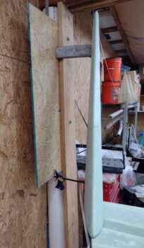
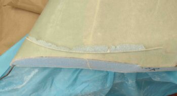
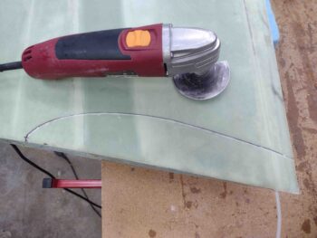
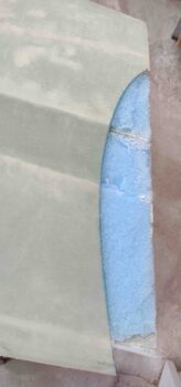
Here I’m re-cutting the left winglet on the newly traced contour line to obtain more of a significant curve on the very front of the winglet.
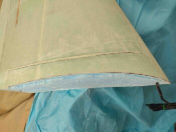
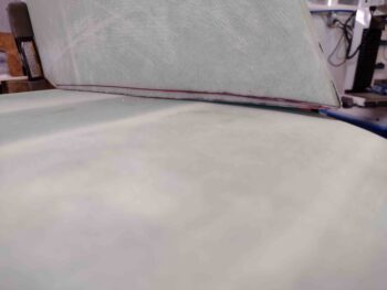
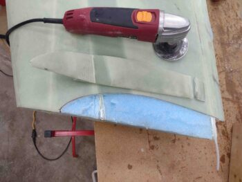
Ahh, much, much better. It may be hard to tell between all the existing lines and the wonky focus on my “updated” camera app on my phone, but the gap is pretty much gone.
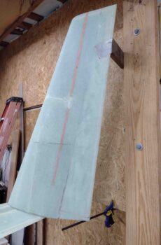
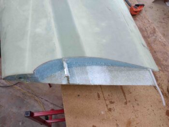
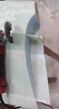
I also re-trimmed the bottom of the right winglet as well, and cleaned up the resulting cut. I’ll note first that I’m losing about 0.2″ in overall winglet height (no big deal) and that I’m leaving the resulting aft notch at the end of the trim line for now because it makes it really easy when placing the winglet onto the wing to just put this notch up against the wing trailing edge resulting in the front winglet leading edge being really close to the 4.5″ and A dimension lines.
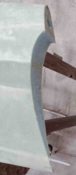
Again, much, much better on fit of the winglet leading edge nose area to the curve of the wing.
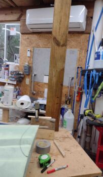
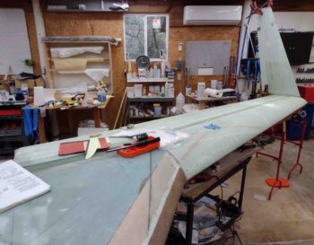
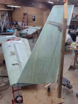
I then reset the left winglet in place and, using the jigs, finalized my A, B, and C dimensions.
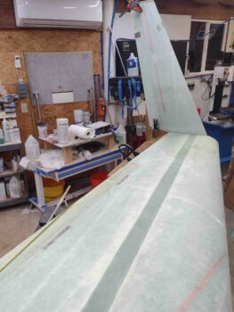
Here’s another shot of the left winglet set in place with the A, B and C dimensions.
I then did the same thing on the right wing end with the right winglet. Here we have the right winglet set in place with the A, B and C dimensions all dialed in.

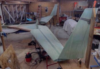
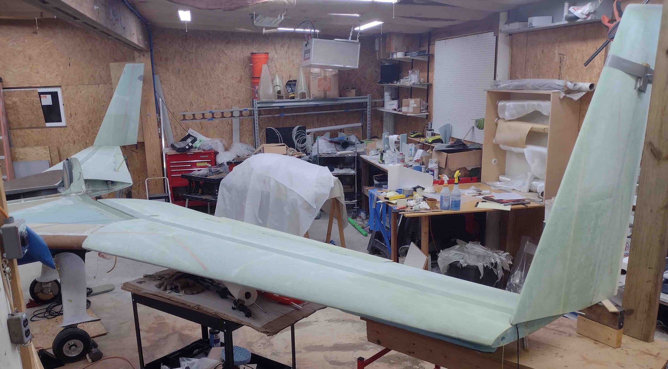
And a few wide angle shots of both winglets with the A, B and C dimensions all set.
I did a final trace of the inboard winglet outline on the left winglet before cutting out the winglet wingtip notch using my trusty Fein saw.
First the top skin and spar cap comes off, then all the foam revealing the leftover shear web.
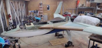
And Voila! the left wing is ready for the left winglet to be set in place for glassing.

I then did the same thing on the right side. I trimmed the winglet outline with the Fein saw, removing first the top skin and spar cap, then the foam to reveal the shear web.
I then cut the shear web and bottom skin to finalize the right wing’s winglet notch.
As par usual, it was quite late at this point so I called it a night. Tomorrow I’ll mount the winglets to the wings with hot glue and bondo. Then hopefully I’ll get at least one wing removed and flipped over on a workbench in preparation to do the inside winglet layups.