
I’m going to start the blog off today by thanking and giving huge kudos to Ary Glantz for catching something that I think 99% of us builders miss. You can read the detail here on his blog. Moreover, since Ary did such a great job covering it, I will simply quote his words below, which is the lion’s share of the detail in his summation of what Jim Weir of RST engineering —the guy who designed the antennas and created the kit that I’d think over 90% of all canards use— had to say about our rudder return springs (indirectly):
Ary:
***** “Ok, so now to install [the rudder return spring] inside the winglet. The “high performance rudder plans” says to install the assembly at WL25. HOWEVER, the RST-2802 antenna manual (the Holy Grail manual that explains everything you ever wanted to know about canard airplane antennas) says “If there is a piece of metal more than an eighth of a wavelength long within a quarter wavelength of the plastic plane antenna design, the antenna performance will be degraded”. They go on to say “with the classic dipole ‘rabbit ears’ design, metal close to the center of the antenna where the ears come together has practically zero effect. Metal out at the tips of the ears has a tremendous effect.”
Hmmmmm… but the High Performance Rudder plans tell us to install a blob metal object at the tip of the antenna! Nooooooooo!!! Why!!!!?!?!!” *****
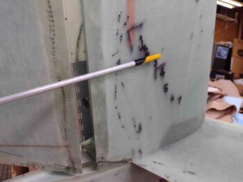
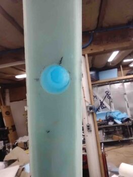
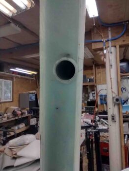
Here’s W.L. 25 on my bird, about an inch down from the bottom tip of the antenna. So “why?” indeed.
My question was if essentially every builder and every Long-EZ that I know of —past, present and recent— installed the rudder return spring per plans, why are there no complaints on radio performance or range? l searched all the CSA articles and didn’t find any instances of issues or complaints.
I also read the RST-2802 manual firsthand and found the answer. As Jim points out, and I”m paraphrasing, if you start out at a certain baseline capability, and it isn’t awful, with nothing to compare it to how could/would you possibly know or ascertain experience-wise how good it has the potential to be? It’s simply a matter of optimization, not just if it works or not.
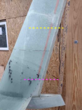
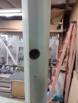
With Ary’s reminder of Jim’s words of warning, I decided to simply move my rudder return spring up much closer to the center of the comm antenna on each winglet. I did want the rudder return spring near a “hard point” so I went a few inches above the center hinge position, which turned out to be about 2″ below the center of the antenna. I think I’m safe in this location… obviously and comparatively much more optimized than putting it in the plans position.
The resulting final delta is 25″, moving the rudder return spring assembly up from W.L. 25 to around W.L. 43.
I’m guessing that the W.L. 25 position was based off the original plans squarish rudder, and with so many people at one point doing conversions to High Performance Rudders vs new builds they simply left the rudder spring in the original position. Also remember that these antenna configurations didn’t come into play until well after the first Long-EZs were built, so the W.L. 25 located rudder return spring assembly predates the Jim Weir winglet-located comm antennas. Just my thoughts, I could be wrong of course.
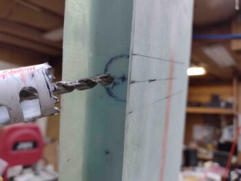
Once I had the positions marked, I took my 1″ hole saw and cut just the glass inside the winglet rudder hinge pocket.
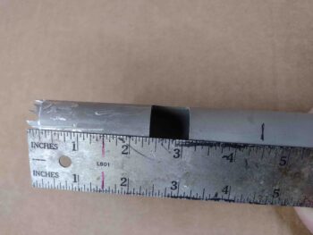
I then found my old lopped off piece of 1″ OD 6061 tubing that had been the original plans length left elevator tubing. It had some left over glass and epoxy on it that I scraped off, and I then notched the end with the Dremel to make some saw teeth.
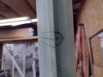
I then carefully used my makeshift hole saw to make the pocket for the rudder return spring tube, being very careful to avoid damaging the antenna copper foil tape… as you can see here on the left winglet.
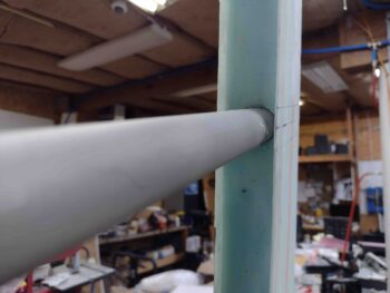
Again, on the left winglet, I cleaned out all the foam to ensure a nice 4.5″ deep pocket, also ensuring that the antenna was not damaged in the process. I did the same on the right side.
I then whipped up some micro and slathered up the inside foam of each winglet cleared-out rudder return spring tube shaft. After cleaning them with acetone, I then slathered up each rudder return spring tube with miicro and stuffed them into the winglets. Although not shown, I also used a nice dap of flox on the wood plug at the front end of the tube before installing them.
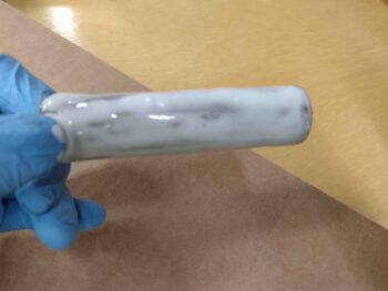
Here we have the rudder return spring tubes micro’d and floxed in place in both the left and right winglets.
While the rudder return spring tubes cured in the winglet pockets, I then turned my sights on installing the rudder side rudder return spring hooks.
If you remember, I made my hooks so that they actually go into a hole on the face of the rudder hinge pocket, before then making essentially a 90° turn to lie somewhat flat against the interior side glass of the hinge pocket. I also made them long enough and canted the hook at an angle that when I install them into the hole, I pivot them to lock the somewhat diamond shaped hook body up against the interior skin on the opposite side of the rudder.
Since the plans aren’t overly clear on how these are shaped, I got the idea for my hook design from how Dave Berenholtz made his (thanks!) after I pondered on their function a bit.
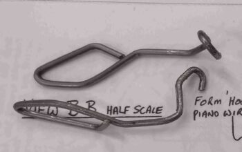
I then made a hole just a hair smaller than the widest part of the “diamond” part of the inside hook body. For the left rudder this was a 1/2″ hole, for the right around 0.46″ diameter hole.
Given how my rudder-side rudder return springs physically lock into place inside the rudder hinge pocket, I wasn’t squeamish about using the decent amount of flox and micro I had left over from the winglet rudder return spring tube installs.
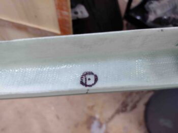
However, just to make sure all was secure, and cover the rather large hole I made on the face of each rudder hinge pocket, I did layup a small ply of BID around each hook. I then peel plied each layup.
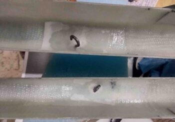
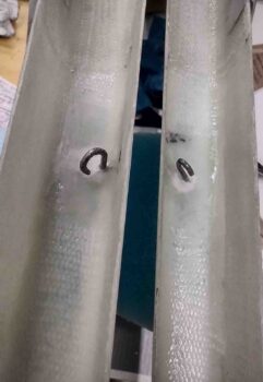
Very much later tonight I pulled the peel ply and grabbed this shot of the rudder-side rudder return spring hooks.
It was too late to install the rudders and test out my spring action, plus I wanted to give the micro, flox, and layups a good overnight cure before stressing them… so tomorrow I’ll test out the springs.
With the rudder return spring assemblies installs complete, I called it a night!