
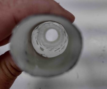
This morning I started out by trimming the glass on the front entrance and aft exit of the oil heat RAM air scoop, then pulling the peel ply from the outside surface, and finally removing the bulk of the blue foam to allow me to pull the tape and peel ply from the inside of the scoop. All in all everything looked fine with the scoop.
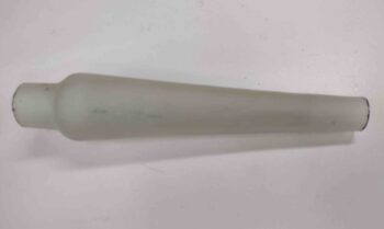
I’ll note that by the nature of using blue foam covered in tape to create an object, the surface inside the object is not going to be perfectly smooth… unless of course you can get at it to sand it down. I’m not going to be that committed on this RAM air scoop unless it simply proves to cause the air to be too turbulent to function.
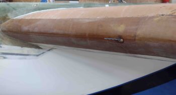
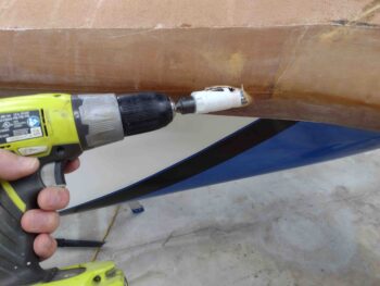
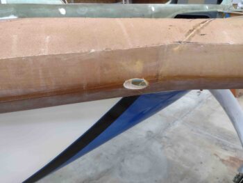
I then pulled the trigger and drilled my pilot hole into the leading edge of the left strake, slightly below centerline, which is where I’ll mount this oil heat RAM air scoop.
I then cut the actual hole with a 1″ diameter hole saw.
With the resulting hole looking like this. I did increase the size of this hole a good bit… I’ll have to get a pic of it later when I finish the RAM air scoop install.
To pull out any moisture or water vapor coming through the RAM air scoop, I’ll send the air through a “mouse maze” in a chamber (enclosed box) containing upward and downward situated tabs. This will help pull out any water and dispense/collect it on the floor of the chamber, where there will be a small drain hole out the bottom of the strake.
I determined this chamber, or “vapor box” that I refer to it as, needed to be 3″ wide x 3″ high x 1.6″ deep. As luck would have it I found the old urethane foam mold core that I used to create the GIB right armrest storage pocket, that is 1.6″ thick.
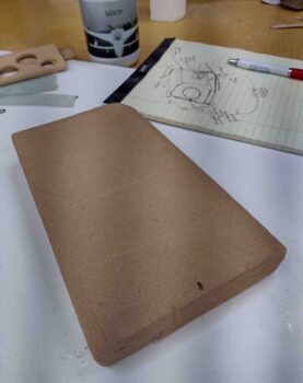
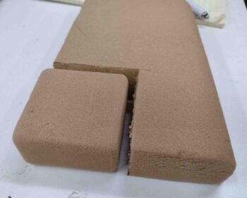
I then simply marked a 3″ x 3″ square, cut it out… and voila! The foam mold core to my RAM air scoop vapor box.
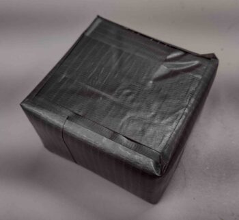
I then taped it up and cut 2 square plies of BID measuring 7′ x 7″ to cover this taped up foam block to create my vapor box.
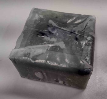
I peel plied the inside, then laid up the 2 plies of BID. Then peel plied the outside. To keep the layup from getting epoxy all over my white work surface, I put a piece of plastic on the work surface. Well, the BID kept wanting to separate from the taped foam form, so I simple cut the plastic as if I were wrapping up a gift box and taped the hell out of it to keep everything in place. I then left it to cure.
This is the aftermath a few hours later.
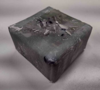
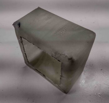
I pulled the plastic and tape off to reveal this… which is the side where all the ends of the BID terminated. This side will eventually get closed in with another 2 plies of BID and get attached to the left BL23 rib (outside wall of the baggage compartment).
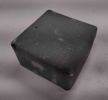
I then pulled off all the peel ply. This is the other side that will face inboard.
I wanted about a 1/2″ flange on the open ‘working’ side that will give me a lip to layup the final 2 plies of BID that will seal up this box when all the internal stuff is created inside.
I then cut the internal square with the Fein saw and cut the foam deep.
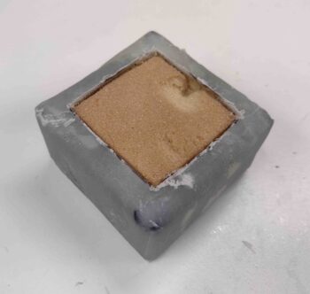
I then popped out the center block of foam and started removing the rest of the foam bits.
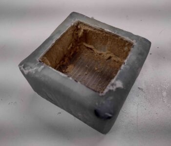
I then pulled out the tape and finally the inside peel ply to reveal the beginning shell of my RAM air scoop vapor box.
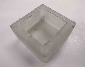
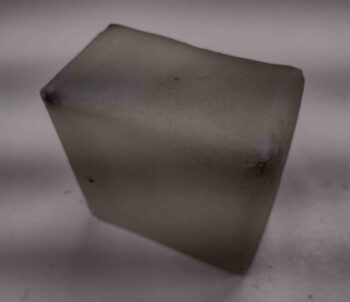
Here’s another couple of shots of the RAM air scoop vapor box shell.
And with that, I called it a night.