
This morning starting off I spent a good half hour updating all my task & sequence lists… some of my individual chapter to-do lists and my overall project plan (what I call my Order of Battle <grin>).
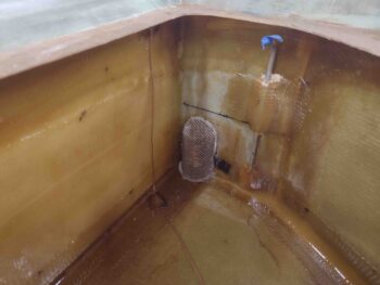
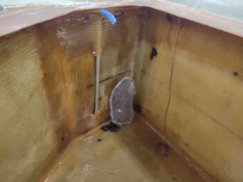
Out in the shop I pulled the weights off the main fuel tank drains’ stainless steel mesh strainers that I floxed in place last night. Everything looked good with these so I taped them up with blue painters tape to keep the dust out.
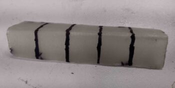
When I did my final layup on the GIB air vent duct last night I had also set up a prepregged layup of 3-plies BID with peel ply on each side. I then placed it on the taped edge of a piece of 3/4″ plywood stood up on that edge. I then sandwiched that between 2 weights and put a shot bag weight on top of the piece of plywood to weigh/squish it all down. I went to take a pic but all you could see was a pile of weights. Here’s the result.
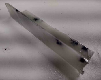
This piece of peel plied 3-ply BID 90° angle is around 3/4″ on each leg, and a hair over 4″ long.

Today I pulled the peel ply and trimmed the edges with the Fein saw.

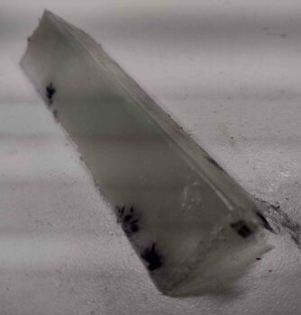
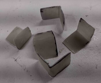
And then made hash lines about every 3/4″.
I then cut the 3-ply BID 90° angle on the hash marks and cleaned up the edges with my sanding block.
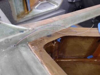
I’ll flox 2-3 of these on each side to support the inside long edge of the upper strake skin when I close out the top strakes. I temporarly taped a couple of them up here on the sidewall to show what I mean:
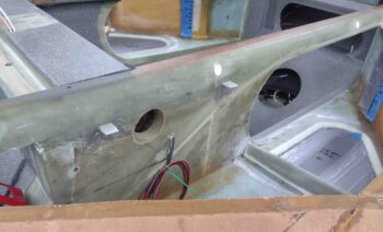
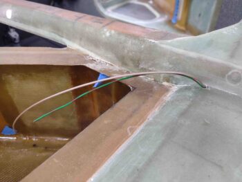
I then knocked out what should have been a fairly quick task, but the left side gave me some unexplained fits that seemingly defied physics (sigh) . . . I drilled a ~5/32″ hole on each side of the upper CS spar where it meets the upper longeron.
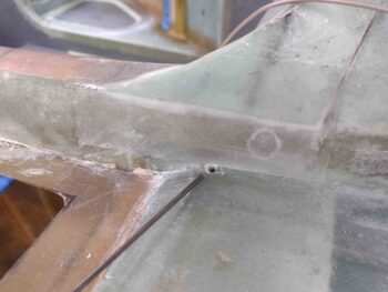
I then threaded the Nick Ugolini fuel probes’ ground wire + signal wire for each respective side up through each hole. Again, the right side took literally 10 seconds, whereas the left took an inexplicable 10 minutes —replete with the usual wailing and gnashing of teeth— since the second wire was hanging up somewhere internally in the hole. But I prevailed!
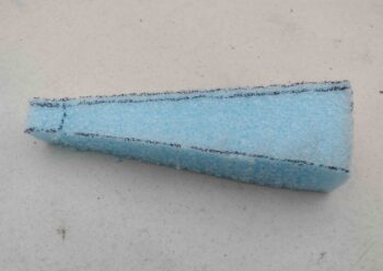
The next task at hand was one I wasn’t particularly looking forward to… creating a blue foam mold for the left strake leading edge located RAM air scoop for the oil heat system. This RAM air scoop will feed the engine-oil fed heat exchanger with pressurized air via the ductwork to provide the Holy Grail of convenience in these birds (if it works!): HEAT.
The key to this entire oil heat system is marrying pressurized air with a good heat source. If my oil heat system plumbing proves good, then the other half required in this dynamic duo is this RAM air scoop. The concept is to take fast moving air, slow it down while minimizing turbulent air, to then provide pressurized air into the air ductwork to transfer the heat from the heat exchanger to the various pilot & GIB feet & face air vents.
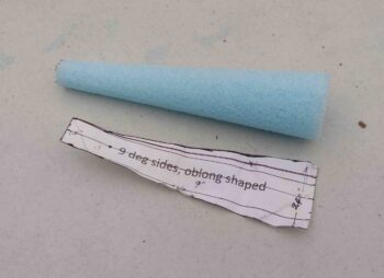
The specific key to the RAM air scoop configuration is keeping the internal angle at no more than 11° between the sides. Admittedly, I’m very close to that max angle since I want to be aggressive with a smaller air scoop in transferring air velocity into air pressure.
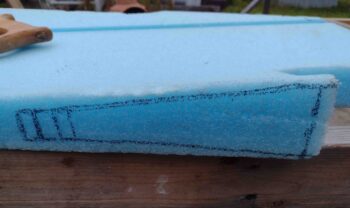
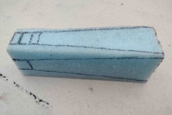
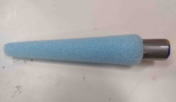
Clearly what we have here is the machinations I went through to take a chunk of blue foam and slowly transform it into a stretched conical air inlet tube, or a foam mold/plug for one I should say.
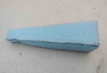
I’m not an expert in airflow, but I know one should have a back “wall” of the tube to create a plenum effect before sending the pressurized air on its way. I made my exit nozzle on the RAM air scoop just a bit smaller than the cross-section of the rest of my air ducts. I might have should have made the exit duct even a bit smaller, but I plan on making this RAM air scoop somewhat removable to allow for experimentation of various design configurations.
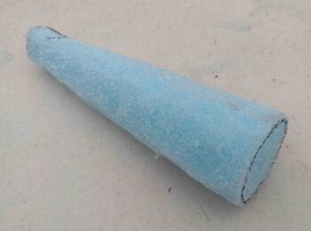
So this is essentially what I came up with… a blue carrot!
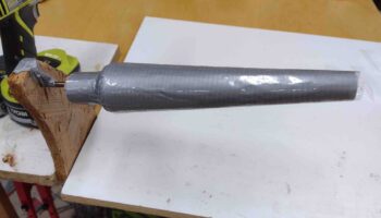
I then taped up the blue carrot and set ‘er on a long 1/4″ drill bit as a sort of glassing spit.
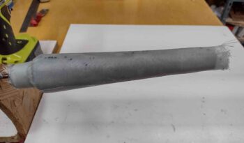
After laying in some peel ply at each end, I then laid up 2 significantly overlapping plies of UNI covered by 1 ply of BID.
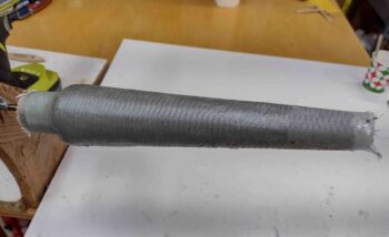
I then peel plied the layup. Since I used MGS 335 epoxy with a mixture of fast & slow hardener, I don’t expect this layup to be cured until tomorrow morning. Thus, I did one final check and left it to cure overnight.
Tomorrow I plan to start on the other components of the oil heat RAM air scoop intake system as well.