
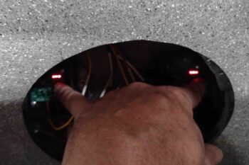
I started off this morning checking the mode my fuel probe electronic control modules are running in… to do so you need to hold down the button and look at the 3-LED bank to ascertain what mode it’s in. The 3 constantly lit LEDs tell me that these modules are operating in the 5S (set point) mode, which means it will be expecting me to program EMPTY, 1/4, HALF, 3/4 and FULL fuel level set points.
When I queried Nick Ugolini on which mode is best for my Grand Rapids EFIS/Engine Management system, he told me that 2S is the best for GRT. The 2S mode is looking for basic EMPTY and FULL fuel level set points, and then the other fuel levels can simply be programmed in the GRT EFIS software.
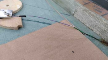
To swap from the default 5S mode to 2S mode, the yellow data wire out of each fuel probe electronics module must be grounded before the sequence to switch the set point mode can begin. And although my fuel probe electronics modules are just inside the GIB back seat access hole, they are wired up all the way to the GRT EIS-4000 25-pin D-Sub connector residing in the GIB headrest.
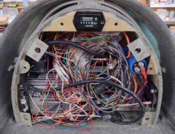
I pulled the cover off the headrest to reveal somewhat of a rat’s nest of wires, but found my 2 wires in a matter of seconds. As an aside: I actually discovered that my current 25-pin D-Sub connector was unable to hold one of these data wire D-Sub sockets securely in place, and the entire connector will need to be swapped out.
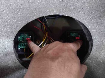
With the data wires grounded, I proceeded to follow the steps to swap the fuel probe electronics module into the 2S mode. This is denoted by the outboard LED lights constantly on, while the middle one flashes red. I grabbed a few pics to get one showing the middle LED light “blinking” … step one complete: now in 2S mode!
I had gone to the airport earlier today to grab a gallon of 100LL. The weather today was light rain which was perfect since the airport was very slow and I was able to get right in to get my AVGAS. I then stopped by my local convenience store to pick up some Corona Lights to use as my requisite fuel container <wink>.
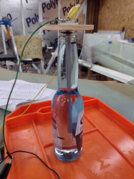
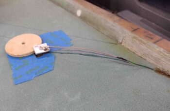
I pre-calibrated my fuel probes one side at a time by starting with just enough fuel in the bottle to have the tip of the probe just barely into the 100LL. Note that I’m using a wooden disk to secure the probe so as not to have anything conductive touching the probe and potentially throwing off the reading.

The initial EMPTY fuel level set point takes about 16 seconds to process, whereas the FULL fuel level set point is finalized in just a couple of seconds.
With the fuel level set points programmed into the electronics modules, I then got busy physically wiring up the fuel probes. I had pre-terminated the included ground ring terminals on lengths of wires to connect to the wires exiting out of the CS spar… in my rushing around to get the probes installed, I had mixed up these wire leads on the left and right probes, so just the wires coming off the probes are actually the color of the opposite side. No big deal, especially since these will get buried in the foam and no one will know except you and me… shhhhh!
I had meant to switch the wires back to the correct side, but didn’t realize the wire color swap again until after I had cut this wire to length to splice and solder it in place. Oh well… again, it will all get buried and works.
Here’s the left fuel probe ground wire spliced and soldered.
And the left data wire cut to length and soldered to the center sensor probe. The left fuel probe here is ready to be floxed into the strake skin, as is the the right fuel probe in the second pic below.
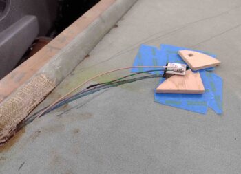
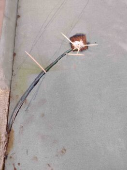
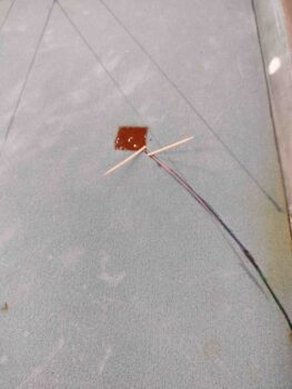
Using somewhat dry flox, I placed it around the perimeter of each notch in the strake top foam… the goals here are to keep the flox from squeezing through the hole and clogging up the vent holes at the inside top of the probe, to seal the edge of the probe base plate to keep the later wet potting flox from seeping into the tank and thus potentially clogging those vent holes, and of course securing the fuel probe in place.
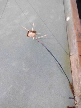
I kept the probes down in their respective notched holes with toothpicks and left them to cure for a few hours.
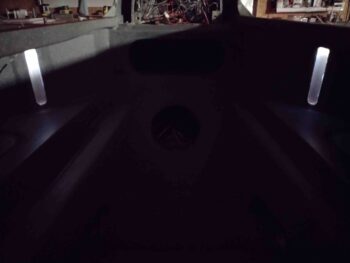
While the fuel probe flox was curing, I fired up the fuel site gage LED lights and turned off all the lights to see what they would look like in near total darkness. Pretty cool… I love ’em!

I then wanted to see how they looked in more ambient lighting, so I flipped on a far light. Again, they look great. I’ll note that in the original install instructions, Vance noted that the LED lights were red… thank God he decided to go with this color! Much better than red! (IMO)
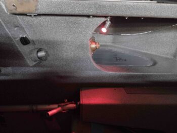
Speaking of red LED lights, I then wired up the GIB map light and fired it up as well. The default light color I have set when this comes on is red… of course to save night vision.
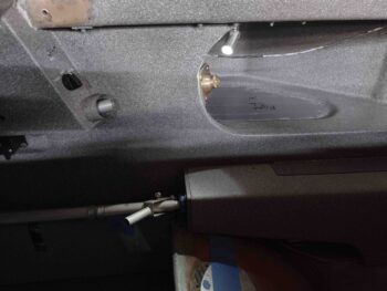
Here’s the GIB map light on its white setting.
Again, nearly 4 hours later I pulled the toothpicks, whipped up some wetter flox (all EZ Poxy on these fuel probes is with 87B hardener) and finalized the potting of the fuel probes in the strake skins.
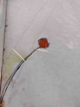
I left a couple toothpicks in place to keep the wires down and secure, and thus the center probe nice and snug against the base of the fuel probe body.

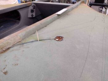
I then left the freshly flox-installed fuel probes to cure overnight.