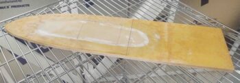
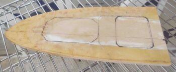
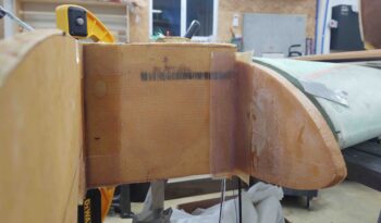
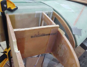
I started out today measuring and marking up my left side OD rib for a significant trim in length. As I just did on the right side, the left OD rib has been modified so that the front portion of it will serve as the outboard fuel tank wall. Again, only towards the front. The aft outboard fuel tank wall duty still belongs to the R45 rib.
Finally, the OD rib is getting trimmed in length a significant amount since I am installing it parallel to the R45 rib, not at an angle as per plans.
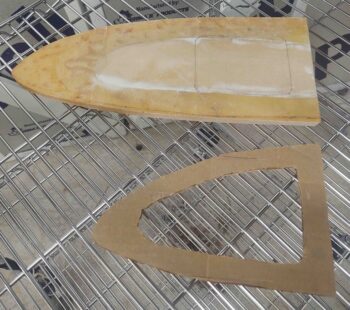
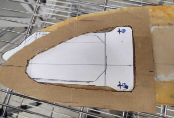
Here we have the modified OD rib trimmed to length, as well as cardboard cutout of the left strake outboard end rib. The cutout is a template to use for the GRT magnetometer mounting plate design to ensure it can pass through the outboard end rib cutout as it gets mounted to the outboard face of the OD rib.
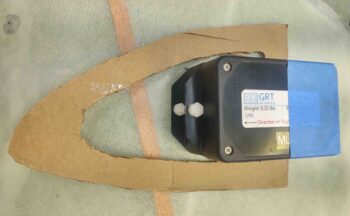
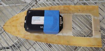
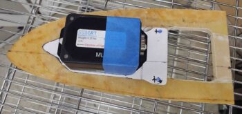
Here I’m double-checking that the stacked GRT magnetometers fit through the left outboard end rib access hole.
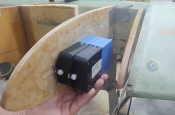
Once I confirmed the magnetometers would fit through the outboard end rib cutout hole, I then set a straight edge along the the front of the ribs to determine how far forward on the OD rib (temp installed at this point) I could mount the magnetometers before the outboard one would contact the inside of the strake leading edge.
To be clear, I want these magnetometers as far forward as possible to get them as far from the antenna cables and wingtip light wires as possible. The cleanest magnetic environment I can create for these things, the better.
I then allowed for a bit of clearance before determining the final install position of the magnetometers on the OD rib.
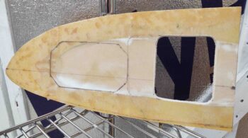
The mounting placement of the magnetometers on the OD rib then required a narrowing of the aft cutout in the OD rib. Again, I’m making a cutout on the aft side to ensure I don’t have a sealed compartment where moisture can build up, and with no way to inspect it.
I then cut out and cleaned up the aft opening in the OD rib.
And again double-checked the fit of the stacked magnetometers.
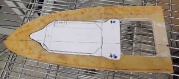
I then spent a good half hour creating a paper template for the GRT magnetometers’ mounting plate. After finalizing the design, I then tested/refined the design on the actual OD rib.
And also ensured there was clearance between the magnetometer mounting plate and the outboard end rib cutout, using my temp cardboard template.
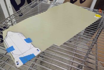
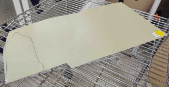
I then taped the magnetometer mounting plate template to the face of some 1/16″ thick phenolic G10 stock and marked the outline.
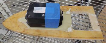
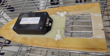
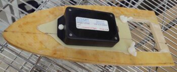
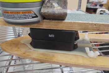
I then cut the magnetometer mounting plate from the G10 stock and cleaned up the edges. On the aft side I drilled 2 x 1/4″ holes for nylon thru-bolts. I then secured the bolts with wing nuts. As per the GRT manual, I’m using nylon hardware as to not induce any magnetic signature around the magnetometers. Brass or aluminum hardware would have been fine to use as well, but the nylon was available, inexpensive and will certainly do the job required.
I then drilled and countersunk a screw hole for the aft side attach hole of the magnetometer. Then did the same (but not CS) for the front attach hole.
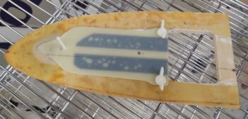
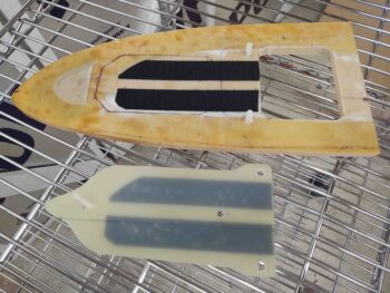
I then trimmed and attached 2 horizontal strips of velcro to the aft side (inboard) of the magnetometer mounting plate and the outboard face of the OD rib.
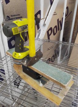
Here we have some weight being applied to the sticky-backed velcro that was applied in between the back of the magnetometer mounting plate and the OD rib outboard face.
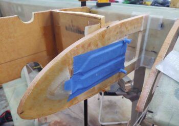
I then taped up the front pointy nub of the magnetometer mounting plate with clear packing taped and laid up 3 plies of glass (BID+UNI+BID) over it to create a tab, or pocket, that will secure the nose of the mounting tab. Thus, when the magnetometer mounting plate, with magnetometers installed, is slipped into place through the outboard end rib access hole the pointy nub is slid into this tab while the aft end of the mounting plate is placed onto the 2 1/4″ threaded studs (bolts). The velcro acts not only to further secure the magnetometer mounting plate but also as a spacer and cushion between the plate and the OD rib (and also provides a gap for the thickness of the front magnetometer securing bolt, which is a thin-headed bolt rather than a counter sunk screw).
Here’s what it looks like with the magnetometer mounting plate off of the OD rib. Note that I worked the velcro a fair bit to remove the air bubbles out of the adhesive tape as much as possible (this pic vs above).
I’m going to time travel a bit backwards, since I wanted to show the magnetometer mounting plate glassed front securing tab (or pocket) to say that while that was curing (as well as the wet flox around the head of the nylon bolts to secure them in place, which I failed to get a good pic of….) I did a bit of cable running down the side of the fuselage.
I couple of weeks ago I decided it was best to have the Trio autopilot roll servo cable run its entire length before finishing the strakes. Yes, I’m a wimp when it comes to doing a bunch of what I consider unnecessary work in the GIB seat area post strakes if I can do it all pre strakes.
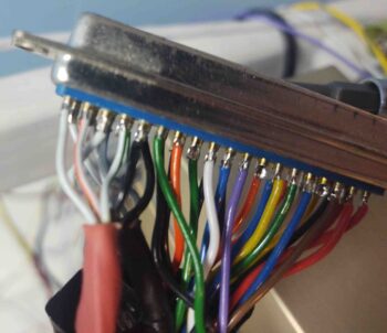
Having said that, I cracked open the Trio autopilot’s control head wiring harness D-Sub connector, located the wires for the roll servo cable and cut them, leaving enough to resolder once I install the actual Trio autopilot control head into the panel.
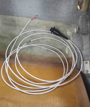
Here we have the Trio autopilot roll servo cable extracted from the wiring harness D-Sub connector and ready to be run down the length of the fuselage.
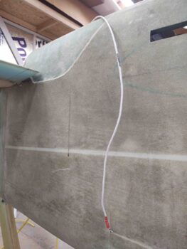
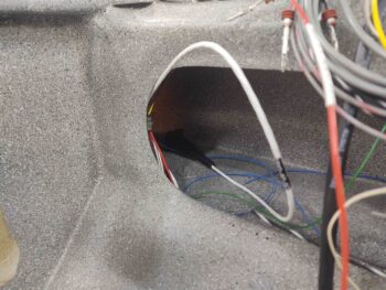
Again, the pics above represent what I did a couple of weeks ago. Today I actually ran the cable from inside the CS spar to the front panel area. I also finished adding 3 more labels to the cable as well.
After running the Trio autopilot roll servo cable, I then ran a loosely twisted pair of 18 AWG wires and a another pair of 20 AWG wires for spare wiring if/when I need it in the future. I was going to add a pair of 22 AWG wire, but decided I had enough with these 2 pairs. So, that completes my wiring runs for the fuselage, and I submit to you all the completed list here:
1. Big yellow power cables (2 cables)
2. 8 AWG B&C alternator B feed
3. #1 6-wire cable
4. #2 6-wire cable
5. Oil heat pump (2 wires)
6. GIB seat warmers (4 wires)
7. Fuel vapor sniffer (3 wire bundle)
8. Trio AP roll servo
9. AEX laser alt (3 wire bundle)
10. SD-8 b/u alternator power feed
11. E-Bus/SD-8 b/u alternator switch
12. IBBS cutoff lead
13. Spare wire runs [1 x 18 ga pair, 1 x 20 ga pair]
14. GRT EIS power lead
15. P-Mag switch
16. P-Mag power
17. Trio AP fuel sensor (2 wires)
18. Electroair power
19. Electroair switch
20. Electroair tach select
21. GRT EIS tach select
22. B&C alternator “F” lead
22. Wing taxi/landing lights (2-conductor shielded cable)
23. Wing nav/strobe lights (2-conductor shielded cable)
After my brief interlude to physically run wires & cables down the length of the fuselage, I then got to work installing the left strake OD rib. Here you can see that the front approximate half of the OD rib serves as the fuel tank outboard wall. Then a straight aft wall pice in-between the OD and R45 ribs, with the remaining outboard wall on the aft side sitting well inboard at the aft end of the R45 rib.
I used a 2-ply BID tape on the inside corner between the fuel wall and OD rib, with 1-ply BID tapes on the 3 remaining aft corners.
In addition, I used EZ-Poxy on the front and aft side of the aft fuel tank wall (cross piece) where it intersects the OD rib/outboard fuel wall. On the aft side where the OD rib is secured to the front face of the CS spar, I used MGS epoxy with fast hardener.
Again, since the weather is a bit chilly, especially at night, I set a heat lamp up underneath these layups to let them stay nice and toasty as they cured overnight.

