
I didn’t get a lot accomplished today, although I would say what I did do was significant.
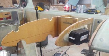
I spent a bit of time lathing and filing the nylon spacer that fits between the front mounting flanges of the two stacked GRT magnetometers. Once the spacer was the correct length/ height I mounted the 2 magnetometers to the G10 phenolic mounting plate, one on top of the other, using silicone RTV and Gorilla duct tape to secure them together in addition to the bolt and spacer on the front side.
Stacking them was really the only viable configuration given the space I had inside the pocket and amount of surface area on the outboard side of the OD rib was less than I hard originally estimated. Since the magnetometers must be oriented with the non-DSub-connector side facing forward, there was only so much wiggle room in how they could be mounted. I had considered making a shelf for them to sit on (they can be mounted vertically or flat) but to facilitate the pre-configured mounting, as a I did here, a shelf structure would have hampered applying BID tapes to the bottom edge of the rib and along the leading edge junction with the bottom strake skin.
I then attached to magnetometers + mounting plate onto the outboard OD rib.
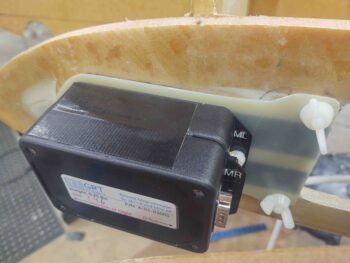
Again, above and below are the 2 magnetometers –GRT HXr and Mini-X EFISs– attached to the mounting plate.
A notable change I came up with is in the wire path runs for these magnetometers. For quite a long time I had planned to run the 6 total magnetometer wires via a 1/4″ diameter Nylaflow conduit running along the lower leading edge of the strake. This path would then travel through the sidewall, via in part along the bottom edge of canopy latch handle opening in the sidewall, and exit into the avionics bay forward of the instrument panel.
However, after re-checking my OD rib angle I concluded it was about 2-3º off of parallel with the aircraft’s centerline. In my research on the GRT site and in my EFIS installation manual regarding the magnetometers’ initialization procedures [which led me to believe the slight offset won’t be a problem… confirming with GRT], I was reminded that the wiring harness for these magnetometers are 20′ long. If that much wire comes ready for install, I say why not use it. So I made a command decision to run the magnetometer wires through the CS spar to join up with the rest of the wire bundle heading from the hell hole, along the fuselage sidewall, forward to behind the instrument panel. This method should prove much easier and way less complicated (read: less time) than running the wires in a conduit through the strake skin and sidewall.
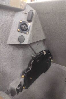
I then spent a good half hour looking for my longer drill bit to drill a small 1/4″ hole in the front lower corner of the right interior CS spar bulkhead, but alas, I couldn’t find it and it was getting late. So I moved onto another task: cleaning up and installing (for good) the oil heat exchanger on the lower left sidewall in the back seat area.
Tomorrow will most likely be focused on prepping the fuselage, and specifically the GIB area, so that all possible tasks are completed before the strakes are built.