
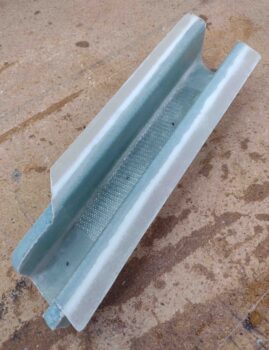
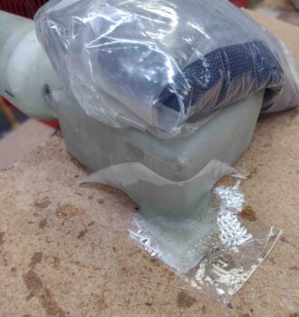
This morning I started out by popping free the oil heat RAM air scoop cross duct/bridge from the clear packing tape I laid it all up on. If you remember, I put peel ply down first before laying up the flanges. I also peel plied both ends for any added plies of glass that will be required.
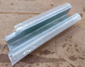
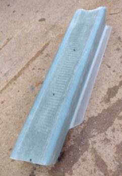
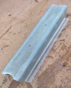
I then pulled the peel ply and razor trimmed the glass. Here’s a shot of the outside, which is actually the bottom of the duct/bridge and the sides of course… a shot each end.
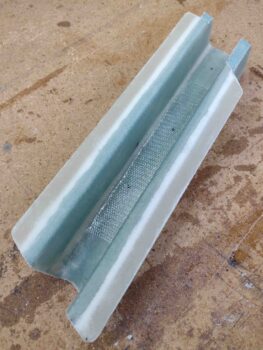
I then took a couple of shots of the inside as well.,, again, from each end.
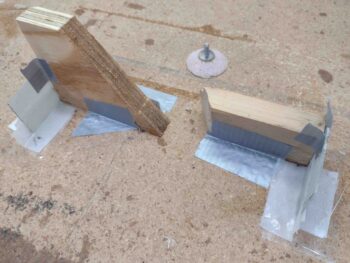
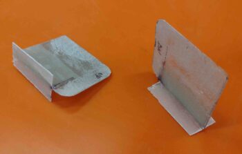
I then got started on the myriad of nitnoy tasks. First off, I made up the vapor fins that will get attached inside the vapor box, the forward one hanging down from the top of the box, and the aft one attached to the floor. This will make the air have to do a couple of slalom weaves to get into the air duct… which should significantly help pull the moisture out of the incoming air.
To assist with laying up the back (outboard) wall of the vapor box, I am glassing mini “T-hats” to the outboard edges of the fins to provide some bridge supports for the backside glass. That’s what all this commotion is in the pic below.
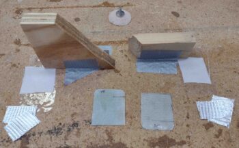
Also, at the very top you can see a spare, previously-glassed piece of 3/8″ PVC foam that I’m using as a pedestal/spacer for the Vapor-box mounting tab Clickbond (see next pic)
. . . the Clickbond to go through this tab which will be attached to the upper aft corner of the Vapor Box with flox & glass. Note that the tab itself is G10 phenolic.
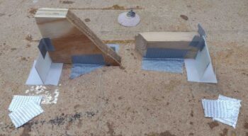
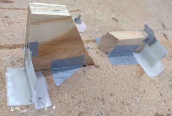
I then mixed up some epoxy, laid up the T-hat glass on the Vapor Box fins and also floxed the Clickbond to its foam/fiberglass pedestal.
Here’s a shot from the other side.
And here we have the Vapor Box mounting tab floxed and glassed into place with 2 plies of BID. I peel plied this layup as I did the T-hats above.
Quite a few hours later I significantly decreased the width/depth of the Clickbond base and then micro’d (since I removed the backside glass) it to the BL23 rib… with just a dab of 5-minute glue in the middle to help secure it quickly.
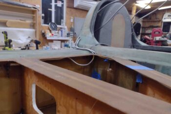
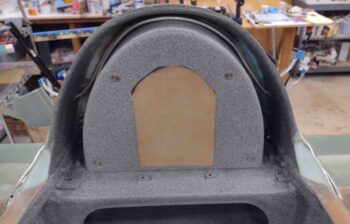
My last task of the evening was actually a REAL build task, as per plans (and CP). I ran the fuel tanks’ vent line tubing from each tank, through/up/over/down the Turtledeck to then pop out the other side. This is how Chris Randall did his fuel vents and it seemed the easiest of all solutions, so I followed suit.
Here we have the right fuel tank vent lines in place.
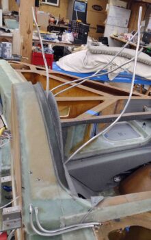
And here’s the forward vent line in the left fuel tank in the top pic, and the aft vent in the bottom pic. I’ll note that with all the extra bending and machinations that I went through to get these vent tubes in place, they are not the straightest or prettiest vent lines you’ll see… but they work. And once the tops are on these strakes hopefully none of us will ever see these ugly things again… ha!
The fuel vent lines coming out from around the GIB headrest reminded me of some sea creature on the ocean floor, tentacles at the ready in search of food… but I digress!
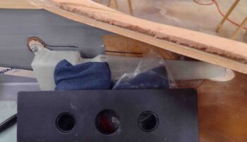
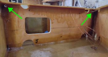
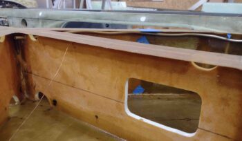
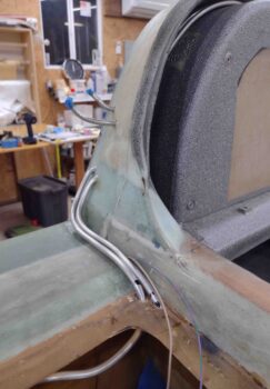
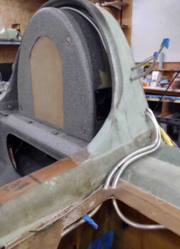
Here’s a shot of the vent lines going through the flange I created to flox the upper strake skin to… note that since I have Mike Melvill’s cowlings that there are shoulder bumps that come forward of the cowling in the corners between the strake and Turtledeck. Thus, to keep the vent lines out of the cockpit, and put the transition holes out of the tank on the top vs the side of the tank, I ran the fuel vent tubes along the aft longeron to then upwards into the Turtledeck.
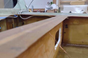
Another shot of the fuel vent line tubing, both on the side of the longeron and entering the Turtledeck. Ok, and the weird stuff coming out of the middle!
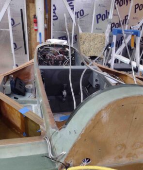
It took a fair bit of finagling to get the lines around the top of the GIB headrest and out the other side, but I eventually got them all. Thank God I gave myself extra length on these tubes, because I tore the ends to hell getting them out of the interior Turtledeck.
After I layup all the extra glass on the Turtledeck for the top cowling mounting flanges and then micro finish it in prep for paint I’ll trim the fuel vent lines flush with the surface of the Turtledeck. Again, this is how Chris Randall did his and he has a ton of years of trouble free flying with his fuel vent tubes configured this way.
I’m not overly pleased with how these vent lines look inside the Turtedeck and I am honestly pondering how best to hide them. Regardless, there they are in their current state.
BTW, here’s how those Vapor Box fin T-hats turned out… not bad for a ply of BID each side.
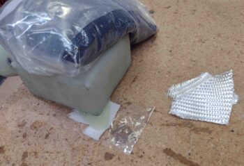
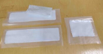
After I did my minor/myriad tasks above, I took a bit of time to make up prepregged 2-ply BID tapes for the duct/bridge when it comes time to glass that in place. I also prepregged 2 plies of BID for the aft/outboard wall of the Vapor Box to close that out.
And with that… I definitely called it a night!