
I spent nearly all day today simply designing, modifying, and creating the oil heat RAM air scoop duct that moves the air from the RAM air scoop/Vapor Box to the upper duct/bridge.
I initially drew up the duct shape on the blue painters tape, then I needed to transfer that to cardboard. I couldn’t find my tracing paper, so I simply used a plastic bag that a buffing pad came in.
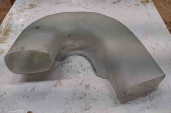
I then transferred the duct shape to some cardboard, made a myriad of tweaks and finally came up with this. I’ll note my standard duct size in this system is 3/4″ high x 2″ wide for a cross section of 1.5 square inches. I didn’t have enough space with this tight U-turn to do my standard dimensions, so I went with 1″ high x 1.5″ wide, clearly giving me the same cross section.
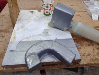
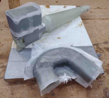
The duct mold is simply 1″ thick urethane foam that I cut and then radiused the top/inboard edges. I then covered it with gray duct tape.
Note the blue rectangle tape on the aft of the vapor box. That tape is also 1″ x 1.5″ but is set inboard by about 0.040″. I clearly needed to make a “ramp” from the vapor box to the duct entrance, so I did that below before I started glassing the duct form.
After creating a ramp at the entrance portion of the duct (left below) I collected all my glass, peel ply, etc. and prepped for the layup.
I also added, shaped and taped a small piece of urethane foam to the bottom of the vapor box that will be a slide in/out removable tray that will hold a sponge for water collection… thus eliminating having a hole through my strake skin.
I whipped up some epoxy and started by adding internal peel ply to the duct mold. I also glassed all the way around the ramp entrance (over peel ply) since it will not be attached to the BL23 rib like the rest of the duct.
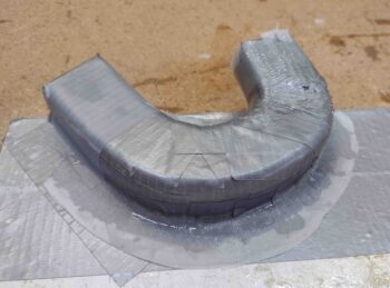
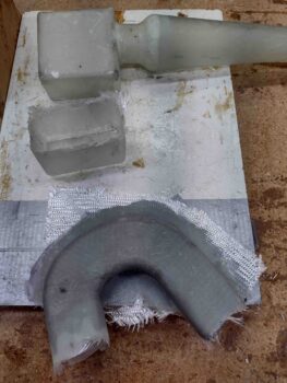
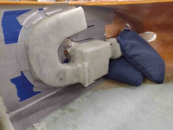
Here we are a couple of hours later with the duct glassed as well as the vapor box water collection tray.
A few hours later I pulled the water drip tray off the vapor box completely, and also pulled the peel ply from from the duct form.
Here’s a shot of the other side showing the peel ply pulled from the duct form layup.
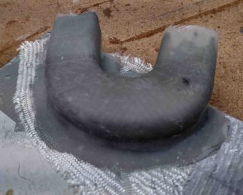
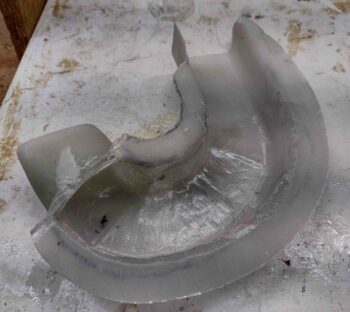
I then pulled the duct form out and trimmed up the glass. Here’s a few shots of that:
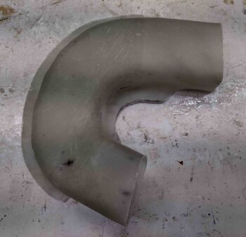
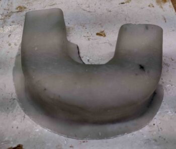
And the inside with the duct form and peel ply removed.
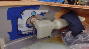
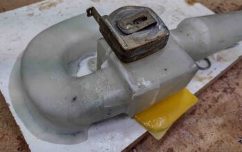
I then quickly mounted the RAM air scoop/vapor box to test it with the drip tray in place.
I then removed the drip tray and test fitted the newly glassed duct segment. With the duct piece in place, I marked the outline of the intersecting duct to the vapor box.
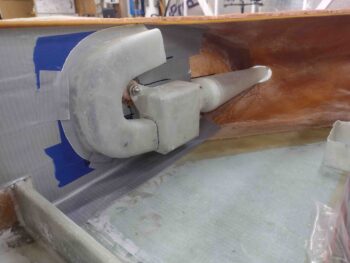
I then cut out the marked duct on the aft end of the vapor box, and glassed the duct segment to the vapor box on 3 sides: the top, inboard (facing up) and bottom. I’ll glass the outboard side tomorrow.
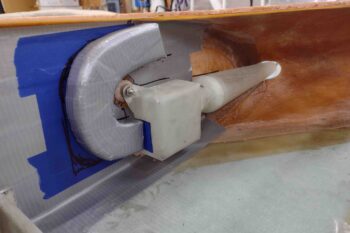
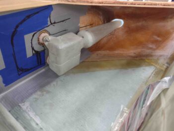
After about an hour cure time, I re-installed the RAM air scoop/vapor box/duct segment to ensure the configuration was correct and locked into place.
It doesn’t seem like it should have taken that long to simply create the duct form and then glass it, but there were a key number of intricate details at play that required a number of re-tweaks… but she’s done now. Let’s just hope it works as designed!