
I have to say that sometimes when I go to write the day’s blog post, the pictures I upload don’t really capture the story of how busy I was for the day, and today is one of those days.
I started off today by grabbing the length of 2 gauge welding cable I have that will make up the primary feed from the battery to the battery contactor. IIRC I went with 2 AWG cable because in trying to locate a source of supply, the 2 gauge was significantly cheaper than the any other size in that general range (at the time at least) so pulled the trigger on it. I wanted at least no less than 4 AWG, and when I ran across this piece I snagged it. Moreover, since I’m using the lighter weight copper-clad aluminum for the big starter cable run & ground return, it’s slightly thicker than normal 4 AWG wire and uses 2 gauge terminals, which I then in turn used some of these same extra terminals for this length of 2 AWG wire.
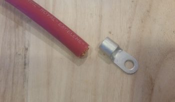
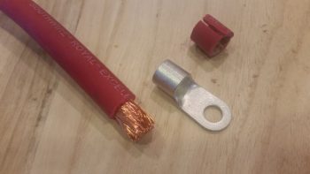
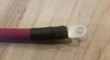
I stripped the end of the battery cable insulation back about 5/8″. I should note that getting the terminal over the myriad of fine wires of the welding cable proved not only challenging, but did require some judicious paring down of some the perimeter wires to allow me get the terminal slid onto the exposed wire. I had thought about possibly needing a wedge or two of copper to drive into the mass of wires from the exposed end (a Bob Nuckolls trick) to better secure this terminal (the same principle of securing a hammer/mallet/axe head to a wooden handle) but the effort to get this thing on was so intense, and the mass of wires so tight to begin with, there was definitely no need –or room!– for any wedges.
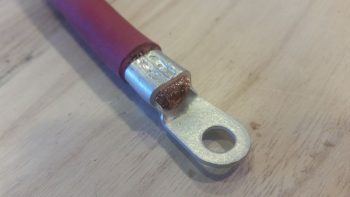
I then took the battery cable with attached terminal down to the garage, and once again used my Molex “crush-it” crimper in the vice to crimp the terminal in place . . . whew, was that quite a workout! Since the base ring is so wide on this terminal, I set it in the crimper jaws again closer to the insulation and this time tried my hand at simply whacking it a couple times with my 2.5 pound mallet. Worked a treat and the double crimp seems a bit more uniform along the entire side of the terminal base ring.
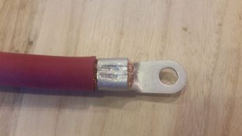
Here’s another shot of the crimped terminal on my battery cable.
I then went on the search for some suitable diameter heat shrink. Here, simply because the cable is red, I made an attempt to use red heat shrink as well, but alas, I only had black in a big enough diameter to cover this terminal end.
I only did the battery contactor end of the battery cable because the battery side will have to be done at final install of all the electrical components in the battery compartment, when I know for sure how all the cables will fit, commingle and get run.
From there I moved on to prepping for the eventual engine storage in my shop. As an aside, I did speak with my engine builder and when he gets an opening in the schedule we’ll finish the engine build. I don’t really mind since I still haven’t cleaned out the space required in my shop, and I’ve been gearing up for taking down another load of stuff to NC in preparation for my eventual move down there later this year. In fact, I’ll be heading down there for about week in just a few days. So if the engine stays up at AERO Engine’s climate controlled assembly shop I have no issues with letting it sit there for another week while I galavant off to NC. I will add to that this is exactly why I started the whole coordination for the engine build back in October of last year because I wanted to allow for the inherent fits & starts we’d have to get the darn thing completed.
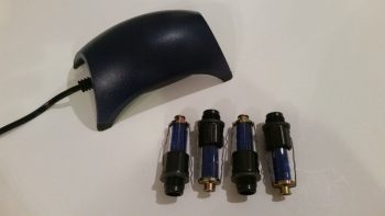
With the engine being a brand new build, it is more susceptible to internal corrosion than a broken in/mid-time engine and requires some prophylactic measures to ensure it remains corrosion and gall free…. as Bill Allen points out in his video on his engine dehumidifier that I included in my last post. Bellow are pictured the 2 primary methods I will employ to help guard against any internal moisture within the engine: A) an active airflow engine dehumidifier (dehydrator) using a small aquarium air pump at the heart of the system, and B) passive cylinder dehydrator plugs that are mounted in the spark plug holes … just one per cylinder.
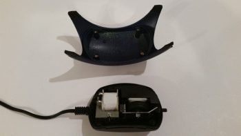
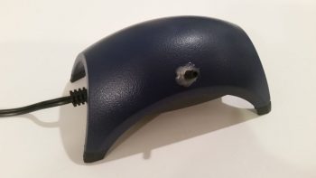
For the engine dehydrator system, a couple slight modifications are required. So I removed the 4 small screws to pop the top cover off.
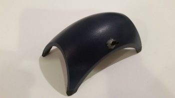
And then drilled a small hole at the center point, near the side edge of the cover.
There was a “T” fitting included with the pump, and since it was the correct diameter for the tubing I would be using, I cut one side of it off to press into service as an air hose barb to turn the small hole I drilled above into an air intake hole.
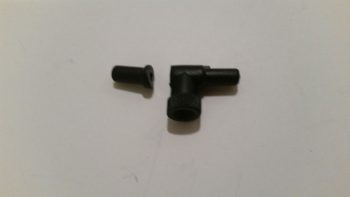
I then used the small drill bit that I used to drill the hole to align the inlet barb with the hole. I then used some 5-min glue to secure the barb to the side of the air pump cover.
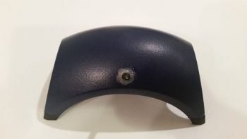
Voila! I now have an air intake barb on the side of my air pump. This will allow the pump to drive air out of the standard outlet that is configured on this pump, and now simultaneously draw air back into the pump through this air intake. This turns a standard OUT-only pump which uses outside air for a fish tank to be transformed into a closed air pump system.
This shot is to show the daylight that can be seen from the inside with the air inlet barb glued in place on the external surface of the air pump top cover.
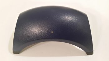
I then reattached the air pump’s top cover and secured it with the 4 screws.
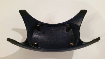
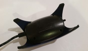
The second and final step required for this modification to transform this pump into a closed system is to tape off the filtered air inlet valve on the bottom of the pump (which somewhat resembles a small upturned decapitated rodent in this pic…)
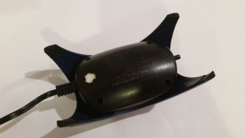
With the application of just a small piece of electrical tape, my out-only air pump has now been transformed into a closed-loop air pump/vacuum (albeit the “vacuum” force created is exceedingly small… this is simply more just an air return inlet).
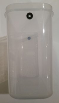
On the engine dehydrator system’s desiccant container I then drilled a 3/8″ hole at the top on each side for the tubing to be run through. I then placed a rubber grommet into each hole.
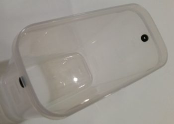
Here’s an end shot of the rubber-grommeted holes on the sides of the engine dehydrator’s desiccant container.
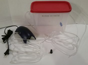
And here’s a shot of the entire engine dehydrator system as it looks so far. I have humidity meters on order and will place an order in the next day or so for the desiccant so that it will be delivered just as I get back from my sojourn down to NC. I would like to especially thank Bill Allen and “Drummer” Dan for providing the specific details via FaceBook on how to construct this engine dehydrator.
I have a few small electrical system tasks that I will continue to work on, but those will dwindle quickly since over the next few days I’ll be gearing up to head down to NC again (as I’ve mentioned a number of times). If possible, I’ll stop by on my way home to visit my buddy Marco to see what he’s up to!
I had to keep reading after seeing the 2AWG wire listed under engine dehumidifier! After your engine goes into service will you continue using the unit… l assume via exhaust and oil filler?
Yes, you know me… eclectic posts! It’s like TV show trailers, they hook you in but make you wait to see it all ;)
Yes, I will definitely continue to use it… I even have a timer now as well! I will probably follow in the footsteps of Bill Allen, et al, by using the oil filler and crankcase breather as my entry & exit points. Then cap off the exhausts with some desiccant bags in the caps.