
Today’s build efforts were marked by a lot of trial & error test fits, measuring and mock-ups in an effort to get all the Hell Hole components integrated and playing nicely together in a rather small area. If you’ve ever seen the TV show, Monk, you can get sense of my emulating Tony Shalhoub “feeling” a crime scene in my efforts to figure out placing components in the Hell Hole. Ha!
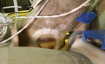
My first required piece of information before I started mixing epoxy was to figure out how I was going to route the big power cables coming from the nose: either above or below the main gear bow. My initial thought was above the gear bow but I just couldn’t get the bend right on the big power cables to miss the sharp edge on the forward gear mount extrusion.
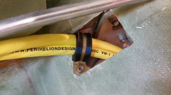
My test run of the big power cables below the gear bow proved much more successful in regards to not having any sharks’ teeth in the way of hard edges at the ready to gnaw through one of these big (which means important! right?!) cables.
Moreover, having to remove and install the big power cables in an Adel clamp in the access hole at the base of the GIB seat bulkhead exposed yet another potential gnawing issue on the rather sharp outboard access hole edge. Thus, I spent a good 20 min with some Perm-A-Grit tools and my mini German hack saw to create a nice round cable-shaped edge in the corner to alleviate any future pain & suffering to my outboard positioned big yellow cable.
I also test routed the return line for my oil heat system a half dozen times to get the right position for the Adel clamp Clickbond hard point. Not only does the Adel clamp secure the oil return line, but it will keep it pressed downward a hair to also avoid the left front mounting extrusion of the main gear.
With my Adel clamp positions –and thus my Clickbond hardpoint positions– known, I pressed forward with setting them in place with 5 min glue. Below is the left side oil heat return line Clickbond on the left aft side of the GIB seat bulkhead.
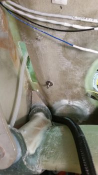
I then glassed it with a 2″ x 2″ 3-ply BID pad….. peel plying it of course.
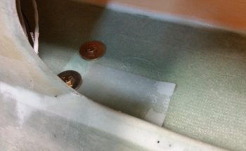
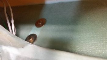
Here we have the oddly positioned Adel clamp Clickbond hardpoint for the 2 big power cables. I placed it on the corner like that to best angle the cables so that they are positioned well for mounting to or traversing through the firewall. In addition, I wanted to minimize the added depth directly below the gear bow here to just the thickness of the cables, and not add the thickness of a bulky Adel clamp.
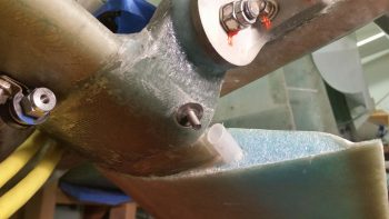
I cheat a bit when it comes to glassing on the gear pads or gear bow and add an extra ply or two, as well as making them oversized, just to take the opportunity to add a bit more oomph to main gear strength. Here is a 4-ply BID pad for the Clickbond that covers about 3/4 of the existing gear mount pad.
With the leftover epoxy I whipped up some thick micro and filled in some open blemishes on my brake line loops… and then peel plied the micro.
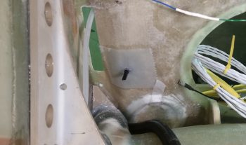
I still had just a bit of epoxy left over (I always seem to make a bit too much when I just get back into glassing after a long hiatus) so I glassed in a 2-ply BID pad that I had planned to put in around the final wire access hole that I’ll drill into the inside floor of the CS Spar.
Here’s the 2-ply BID pad after I removed the peel ply a couple hours later. Tomorrow I’ll glass a 2-ply BID pad on the underside of the CS Spar in the same area. When the hole gets drilled I will be digging out the surrounding foam and creating a flox hardpoint around the hole to reinforce any strength that may be lost in creating the hole.
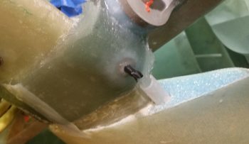
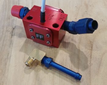
With my shop work done for the evening I headed upstairs to do the final -6 45° AN fitting install on the FT-60 “Red Cube” Fuel Flow Transducer. I wanted the fitting clocked more aligned to the side marked with “FF” but it was just too loose in that position. I checked to see if I had any more -6 45° AN fittings on hand, but I didn’t. So, I took it down to the Hell Hole and checked to ensure there was enough clearance with the fitting situated as it is more up than slanted straight inboard. The clearance is fine –I’m using a 45° fitting to more easily clear the aft main gear mount– but it will mandate that I get a little more creative with my bends on the 3/8″ aluminum fuel line run to the filter. (I also constructed 2 of the 3 connecting wires for the fuel flow meter).
Also pictured is the brass fitting that I picked up from Airflow Performance when I ordered my Sniffle Valve. It looked as if it had a lower profile than the 90° barbed brass fitting that I had on hand for the mechanical fuel pump overboard vent port. In comparing the two fittings, this one looks like it will be a bit more shy and protrude out about 0.15″ less than the barbed brass fitting. Yes, not much, but when we’re talking engine to firewall clearance, every bit helps. Since I had the Loctite 567 out, I went ahead and installed an aluminum barbed fitting into the right angled brass fitting.
Lastly, I figured I would provide a glimpse inside my “evil lair” at what I call poor man’s CAD: paper, pencil, ruler and an eraser!

My final act of the evening was to update the external aircraft lights electrical diagram. Tomorrow I’ll continue my quest to wrap up the Hell Hole configuration so I can get the firewall installed.