
Final prep for installing the firewall that is . . .
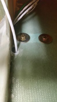
I started out today by drilling a hole inside the CS Spar floor down at an angle from outboard to inboard so that the wiring coming up from the Hell Hole would better follow the contour of the side of the oval opening in the CS Spar. My goal is to have the wires accessible and situated just inside the CS Spar oval opening.
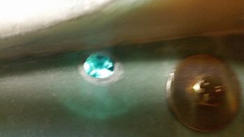
I drilled only through the top layer of glass and then spent almost a half hour digging out as much foam as I could get to, which if you look at the circular empty cavity next to the hole as visible due to a light placed below, it’s roughly the same size as the AN970-4 washer next to it. That’s quite a solid hardpoint considering this foam is 1″ thick [As a point of note I used Divinycell for the spar vs the Urethane called out for in the plans… so slightly heavier spar, but inherently stronger].
I filled this cavity up with about a 60/40 mix of flocro, slightly heavier on the flox, and let it cure before drilling out the hole all the way. In addition, I concurrently laid up a 2-ply BID pad measuring 2″ x 4″ on the underside surface of the CS Spar in the Hell Hole that encircles this hole (I didn’t get a pic of that layup…)
While the stuff above cured, I then pulled the wing lights’ wiring harness back out to wire lace the wires. Once finished I reran the wiring harness through the CS Spar.
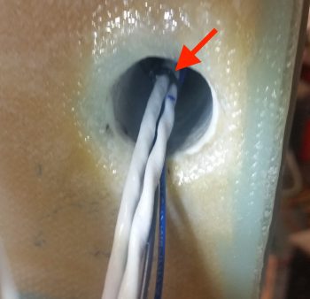
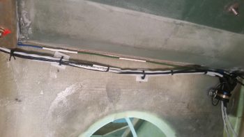
I stopped the wire lacing just shy of each end of the CS Spar (cable lace shown by red arrow).
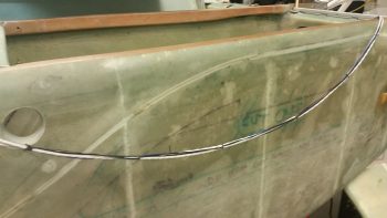
Here’s the right side wing wiring harness cable laced, draped over the left fuselage side.
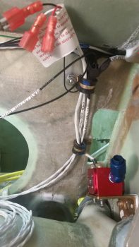
I then cable laced the wing wiring inside the Hell Hole and secured it to the seat back via my plastic wire tie-down points. The loose wire at the top apparently got away from me and at the angle I was working at I simply didn’t see it until I looked at this pic! No worries, I’ll simple secure it as well. I will say that where that loose wire is located is where I was aiming to put the wire tie-down points before the seat “reached out” and grabbed them! Still, the setup works fine and all the wires are nice and secure.
I then test fitted the big power wire runs through the Adel clamp on the bottom side of the gear leg pad. This configuration works really well in keeping the wires from possibly getting pinched or damaged.
I really like this configuration as it looks like it will work really well in keeping the wires from getting gnawed through from any vibration…
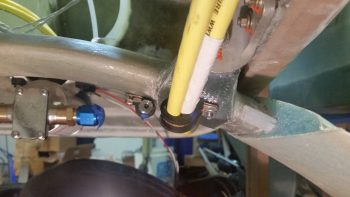
especially at the transition from Hell Hole into the cockpit via the access hole in the GIB seat bulkhead.
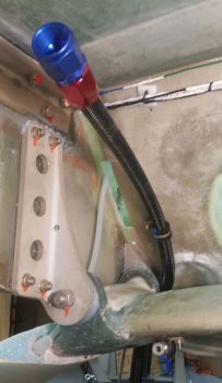
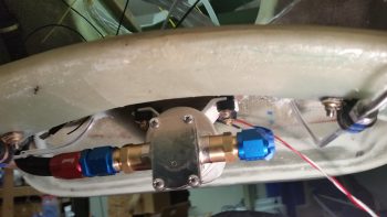
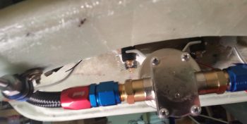
I then did the final install on the FT-60 Red Cube fuel flow transducer. After torquing both AN4 mounting bolts and the -6 tubing AN fitting nut, I applied orange torque seal to the -6 AN fitting. In hindsight I should have applied torque seal to the AN4 bolt heads as well, so I noted that needs to be done.
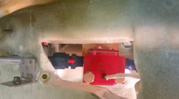
Here’s a shot of the final mechanical install of the FT-60 Red Cube fuel flow transducer.
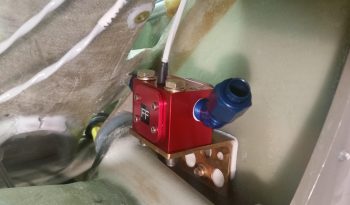
I then added cable management Adel clamp #2 to run the 3-wire cable from the Red Cube fuel flow meter upwards. Again, I situated the Adel cable management clamps in their locations to not only keep all the wiring wrangled, but specifically to keep the wires off the aileron torque tube that traverses this part of the Hell Hole.
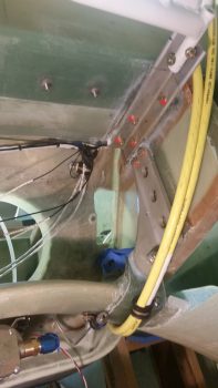
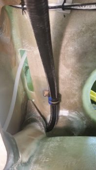
I then ran the 6-wire cable from the Instrument Panel along the fuselage sidewall, through the wire routing Adel clamps in the Hell Hole and up through the lower wire access hole in the CS Spar.
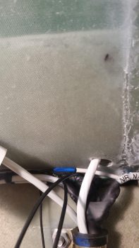
This 6-wire cable contains wires that interface between the EIS4000 in the D-Deck and panel avionics. Here the 6-wire cable is heading up towards the D-Deck/GIB headrest. Note that this hole will serve as the sole remaining access hole on the lower CS spar plate for all wires heading to & from the D-Deck/GIB headrest-based components.
I also did a final install on the oil heat return line Adel clamp.
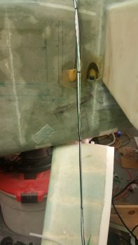
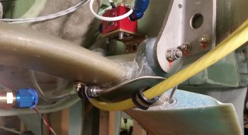
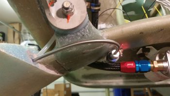
I then spent well over 2 hours shaping, cutting and installing the 3/16″ stainless steel brake line tubing that runs through the plastic tubing channel that I glassed into the gear fairing, situated on the TE of the original gear bow.
Shaping the right side brake line was a little trickier because I had to go up, over and around the big yellow power cables. I had considered looping aft and below the cables, but I wanted as little brake line as possible hanging out unsecured in free space. So I went up and over the big yellow cables. I spent well over 2/3rds of my time working these brake lines on this right one.
The left was significantly easier, although bending stainless steel is not the easiest, daintiest of endeavors to undertake –especially when small bends or curves are required on a small length of tubing. But through persistence I finally got both stainless steel brake lines routed through the gear legs and installed in the 3/16″ to 1/8″ Bi-Lock reducers (thanks to Dave B. for the gouge on those!).
All that is left now (although not a significantly EZ task) is to cut these lines near the wheels and cross connect them to the 9.25″ long -3 stainless steel hoses that are the final link in the brake line chain.
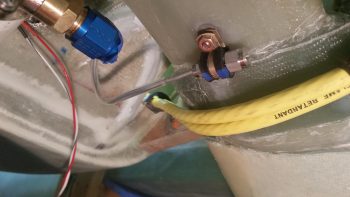
I then did the final install on the oil heat pump on the bottom centerline of the aircraft. I like this pic below because it shows the oil heat pump, finished right brake line and secured big yellow power cables.
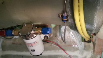
I had to spend a bit of time cleaning cured epoxy off the ends 2 of the 4 bolts hanging down from the oil heat pump, but after that I was able to bolt the pump in place EZ-PZ.
With all the Hell Hole prep work that I was able to finish today, I think I should be able to get the firewall mounted tomorrow….. Inch by inch gettin ‘er done!