
I started off today by pulling the peel ply and razor trimming the edges of the 4-ply BID layup on the front right corner flange of the hell hole.
My plan for the day was to start off by glassing the RAM air scoop, but curiousity got the best of me so I spent the first 45 minutes mounting the nose gear AEX LIDAR laser altimeter on the newly glassed flange.
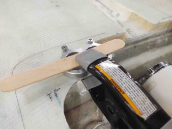
I first determined the laser altimeter’s mounting position and then clamped the aluminum mounting bracket into place.
Since the laser altimeter is meant for a drone, the mounting screw holes on the bracket were only sized for 4-40 screws. Wanting something a bit more robust I drilled the holes out to accept #8 screws.
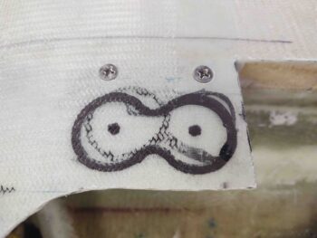
I then drilled countersinks into the flange glass for the screws. And also marked the position of the mounting bracket on the top of the flange.
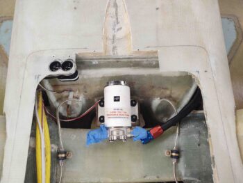
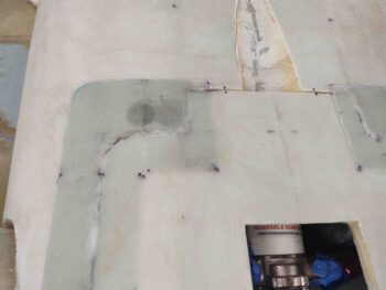
After drilling out the lens holes and sanding them to a good diameter, I then mounted the LIDAR laser altimeter unit onto the hell hole perimeter flange. I also connected up the wiring harness to ensure that the length was good.

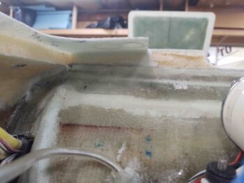
Here we have a shot from above the inverted fuselage showing the newly mounted laser altimeter.
I then set the hell hole hatch cover back into place to get a view of the laser altimeter position through the somewhat clear perimeter flange of the cover. I’ll drill and shape the lens holes in the hell hole hatch cover flange once the RAM air scoop is mounted and glassed into position.
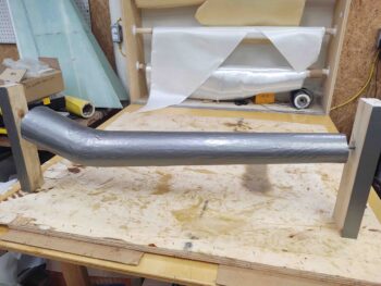
I then constructed a spit to both secure and rotate the taped-up RAM air scoop form to allow me the ability to much more easily glass it.
I then spent the next few hours laying up first a ply of BID (over peel ply), then multiple pieces of UNI for ply #2, and then a final ply of BID.
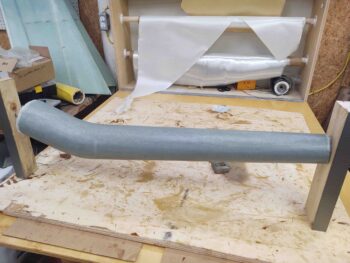
I then finished up the layup by peel plying the entire surface.
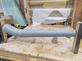
I then left the layup to cure overnight.