
Today I started off by getting the last couple of button head screws pulled off of the landing brake and replaced with countersunk stainless steel screws. Again, I’ll be pulling the landing brake off here shortly when I go to micro finish virtually the entire bottom of the airplane in prep for paint.
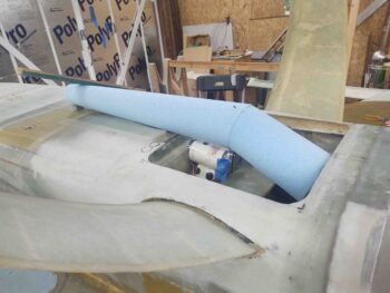
Besides the screw swap out on the landing brake, today was all about finalizing the shape of the belly RAM air scoop and getting it ready for glass. I need a dogleg in the RAM air scoop to bring the air from the scoop –set at an appropriate angle to the oncoming air– down into the hell hole to mate up with the air entry duct of the RAM air can on the front face of the firewall (in the hell hole). This is obvious in my previous pic from yesterday.
To be clear, I don’t know enough about airflow and fluid dynamics to know if this dogleg, bend, elbow, kink (whatever you want to call it) is a big no-no for what I’m trying to do here. I was discussing the possibility with Marco that since I had to have some curves designed into this RAM air scoop –and that they might negate the velocity-to-pressure recovery I was looking for to increase manifold pressure about 1″ via the RAM air can– I was highly considering scrapping all of it and simply putting a filter hanging off the fuel injection servo and calling it a day. This was before I even cut the bottom of the cowling to allow the RAM air can to fit in place on the firewall.
Well, luckily I had that conversation with Marco, because he noted that Ary Glantz “does this for a living” as a NASA Engineer and recommended that I discuss it with him. Great advice and that’s exactly what I did. As I mentioned before, Ary was very helpful and the bottom line is that Ary’s observations were that the speeds we travel in these birds combined with the somewhat shallow angles of the bends in my scoop, he felt that the pressure drop would be negligible. He also noted that without a lot of time and money it would be difficult to test by exactly what impact these curves would have and by how much. Ary noted that even with the bends in the RAM air scoop the positive affects would outweigh any negligible losses.
So I pressed forward. See?! I actually tried to eliminate a big mod and was talked out of doing so!! ha!
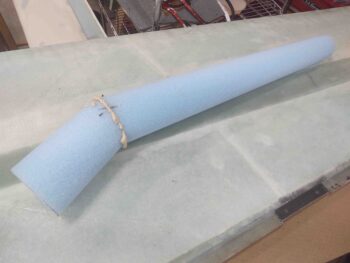
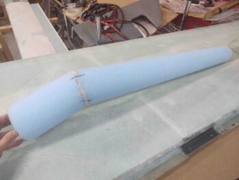
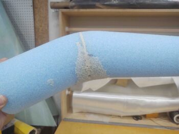
Of course my goal is to attempt to keep a constant increase in width as the scoop widens out as it progresses aft. To create this first dogleg I simply cut the straight RAM air scoop foam at an angle and then rotated the aft side 180°.
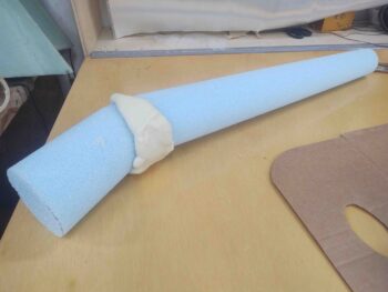
In pondering how to secure the 2 pieces together, and not wanting to mess with micro cure times, I simply used a thin layer of pour foam to act as a glue. I then mated the sides together and secured them with nails and toothpicks.
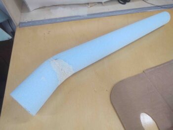
After the pour foam cured, I then cleaned off the excess foam.
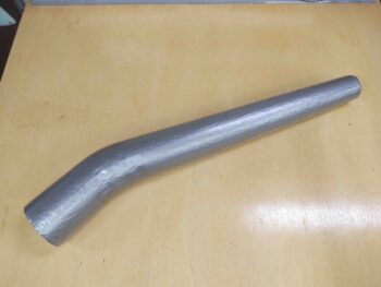
Here’s a couple more shots of the initial dogleg in my RAM air scoop.
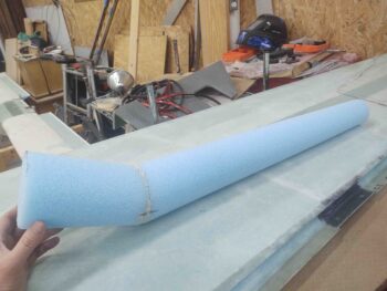
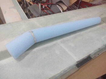
I then rounded the shape on the top side to eliminate the hard angled edge at the dogleg. My next step was to eliminate the negative side of that on the bottom of the dogleg, which of course meant adding in more material. Again, this is in my attempt to keep the ever-widening angle of the scoop constant as the air flows aft. Thus, whatever I shaved off the top then gets added back in on the bottom… roughly.
I poured some foam around the bottom half of the RAM air scoop dogleg junction.
And then, as carefully as possible, removed the majority of it to leave just enough to create a rounded curve –both top and bottom– of the dogleg.
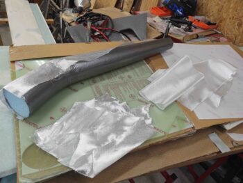
I then taped up the RAM air scoop foam form with duct tape to act as a mold release when I glass it.
I then spent a good bit of time actually cutting the glass for the RAM air scoop. I had originally planned on simply using 3 plies of BID but after assessing my BID supply, and realizing that I will have to order yet even more (amazing how much you go through on these birds!) I decided –after finding a nice angled piece of UNI that covered half the scoop– to cobble together a UNI ply from scrap glass as the middle ply.
It was too late to kick off a multi-hour layup on the RAM air scoop, not even allowing for the time I would need to construct a spit much like my buddy Dave Berenholtz did when he glassed his RAM air scoop (thanks for the idea Dave!).
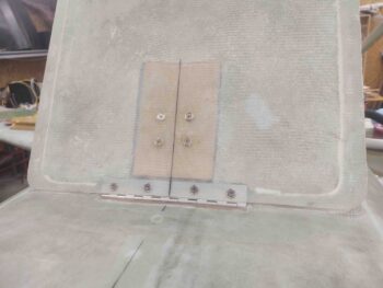
So I decided to narrow my scope and knock out a smaller piece of the puzzle. I cleaned out the foam and glass under the flange on the right front (left as inverted) side of the hell hole. I then prepped the foam strip with micro and created a drier micro fillet along the top corner before glassing in a 4-ply BID prepregged layup. This glass will buttress up that flange and allow me to install the LIDAR laser altimeter that is in integral part of the new gear AEX system.
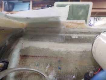
I then of course peel plied the layup and left it to cure overnight.