Today was actually a light build day, for a couple of reasons. First, I had a number of personal errands to knock out. Second, I needed a bit of break from shop work because I was honestly just wore out from constant building.
As I was paying bills, buying birthday gifts, etc. I took some old data & measurement sheets I had made up on the oil heat lever sub-panel to convert it from mechanical levers to electrical controls. I ginned up a CAD model and started printing 0.03″ thick prototypes of the sub-panel plate to begin the configuration and fitting process. As I’ve noted before, it takes a few minutes to kick off a 30+ minute 3D print, so as I went about my non-plane building business, I was at least getting something plane-related done.
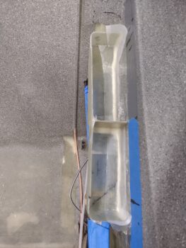
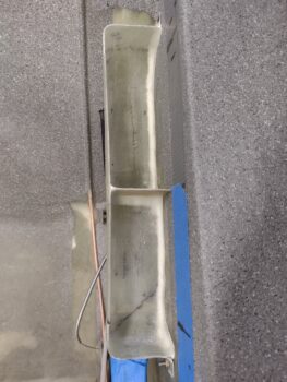
In the shop I started out by making up a cardboard template to determine the size and shape of the left armrest storage compartment middle divider. I then cut the middle divider out of a 1/32″ thick piece of G10 and set it in place with 5-minute glue.
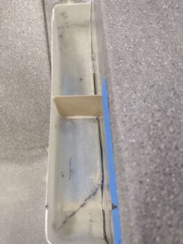
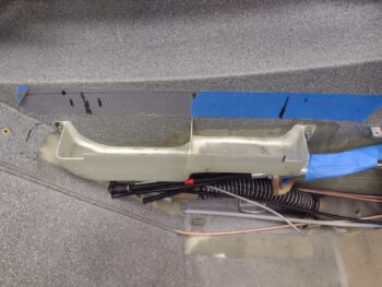
Note the corner seam between the storage compartment and the sidewall, where a decent sized gap exists . . .
In making the armrest storage compartment removable, I wanted to eliminate this gap so that nothing that I was putting into the storage areas were falling into that gap or getting stuck, jammed, wedged, etc.
I started by adding clear packing tape to the fuselage sidewall before mounting the armrest storage compartment in place.
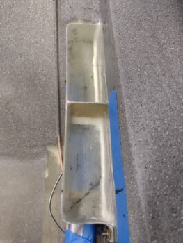
After adding micro fillets in the corners, I laid up a ply of BID on each side of the divider, overlapping onto the compartment floor and sidewall. I then filled the corner seams with dry micro fillets as well before laying up a ply of BID in the corners. I then peel plied all the layups.
As the BID cured ( I nearly always use fast hardener) over the next few hours, I got to work on the oil heat sub-panel (see pics below) to ascertain all that I would need for constructing that. About 4 hours later I pulled the peel ply and razor trimmed the overhanging glass.
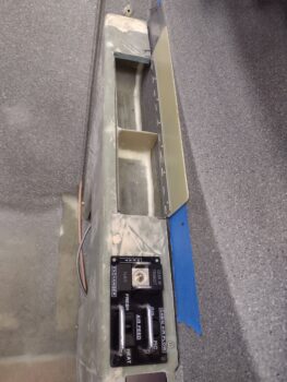
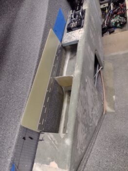
I then pulled the storage compartment off the sidewall and trimmed the excess glass and micro, sanded the edges and cleaned it up before re-mounting it back in place. Here you can see I achieved my desired results by closing up those lower corner gaps so I don’t lose anything I’ve placed into the storage compartment along those outboard side seams.
Here’s another shot of the micro’d and glassed corner seams of the storage compartment.
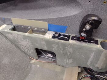
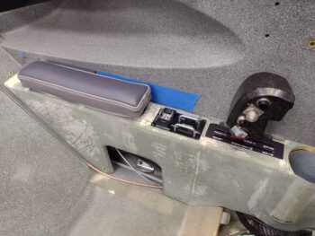
I then mounted the left armrest in place to check out how the storage compartment was looking with its internal area finished. As I’ve noted before, the front compartment is perfect for smaller items like pens and eyeglasses, while the aft compartment provides just a skooch more storage space. The hinged cover is simply wedged in place for a general ideal how it will look/function.
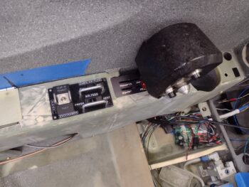
Here I’m also specifically assessing the fit of the oil heat sub-panel mockup. I wanted to verify that the electrical switches and Korry lights didn’t protrude too low as to hit or interfere with the throttle and mixture cables functioning, which thankfully they did not.
Also I wanted to verify the spacing was good with the throttle quadrant in front of the oil heat sub-panel.
Yes, it’s a busy armrest, as is the vast majority of stuff in this bird. Note we have the major left pilot armrest components in view here: storage compartment with hinged cover, oil heat sub-panel, throttle quadrant, and cupholder. The throttle quadrant being a mandatory item while all the others simply add comfort and quality of life whilst flying this bird.
Another shot of the oil heat sub-panel, which will control the 3 micro-actuators that in turn manipulate the 3 oil heat valves: 1) heat exchanger, 2) air feed with either cooling air or heat, and 3) air flow distribution between GIB & pilot.
Unplanned is the shot of the oil heat oil pump PWM controller sitting in the pilot thigh support left compartment (not it’s mounting location) that will control the output/amount of hot oil flowing through the system.
And finally a shot with the oil heat sub-panel mockup in place with the left pilot armrest elbow pad in place to ensure that spacing will work as well. I have a fair number of switch guards on hand and figured this oil heat sub-panel is in a perfect spot to utilize those since it is a high traffic area hand-wise and I don’t want to mess up my heat/air settings once they are set.
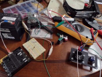
Back in the house I spent about an hour total collecting up all the stuff I needed and then wiring up the 2″ micro-actuator —that I recently bought for opening and closing the RAM air can butterfly valve— as a test subject. On both the RAM air can valve and the oil heat system valves I want open/closed position reporting from the actuators to let me know what state these systems are in.
After about 15 minutes of testing various connections I found what I wanted, with good reporting coming from the actuator circuit that will provide me the manipulation of the AG6 warning annunciator, and main panel/oil heat sub-panel indicator lights. As it was fairly late at this point I’ll update my wiring diagrams with these new circuits tomorrow.
And with that, I called it a night.
