
Yep, today I employed a rudimentary list-form version of the Karnaugh map, or k-map to figure out the circuits going to/from the respective A & B sides of the 3 connectors that I’m using to enable a fairly quick-disconnect of my instrument panel. If you’re wondering what a k-map is, it’s used in Boolean Algebra and reduction to reduce a multitude of circuits down into the least number of circuits possible and still get all the correct functions out of an integrated circuit chip. Or, as that Internet thing puts it, “Karnaugh mapping is a graphic technique for reducing a Sum-of-Products (SOP) expression to its minimum form.”
Although not overly difficult, it was of course time consuming to go through literally every wire & component to ascertain its relationship to the panel. Moreover, since I had finalized all the I/O requirements (yes, this is still an airplane building blog, NOT a computer forum… ha!) for my throttle handle switches, I realized as I was building the new connector diagrams that with a little internal (to the throttle handle) consolidation of 3 ground wires, that I only needed exactly 19-pins for the throttle handle connector. Thus, I could then swap out the 24-pin connector that I had planned on using for the throttle with the now “old” 19-pin connector that I had on hand for the recently put-out-to-pasture GIB Infinity control stick (AKA “the really expensive spare control stick”). The new configuration for my 3 connectors (I’m going to have to come up with a reference name to identify these things! . . . I’m leaning toward the “PQD (Panel Quick Disconnect”) is as follows:
- P6: 24-pin AMP CPC – Thick wires/high power & ground connections
- J3: 15-pin D-Sub – Thin wires/low power & ground connections
- J4: 37-pin D-Sub – RS232 data & low power transfer connections
With the PQD connectors (trying it out . . . ) squared away I then decided that before I put away the Trio Pro Pilot autopilot wiring harness I would cut & terminate the shielded 4-wire cable for the pitch servo. I took it down to the shop and determined the required length. I then cut it WAY shorter than how it comes from Trio. The excess cable that I cut off is visible above the harness in the pic below (post terminated connectors).
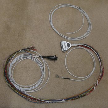
As with shielded cables, I carefully stripped the outer cable jacket and consolidated the shielding wire to one side. After twisting it and cutting it down to about a 0.3″ pigtail, I then soldered a piece of black 22 AWG wire to the pigtail. I then terminated the black pigtail wire in tandem in an AMP CPC socket with the identified ground wire of the 4 wires. I then terminated the other 3 wires with sockets as well. Also, I added a piece of black heat shrink over the soldered joint to protect the joint and add a bit of strength to the cable for when I eventually set the connector cable clamp in place. Finally, as I did with the roll servo cable, I performed an electrical continuity check on each wire to ensure my connector terminations were good.
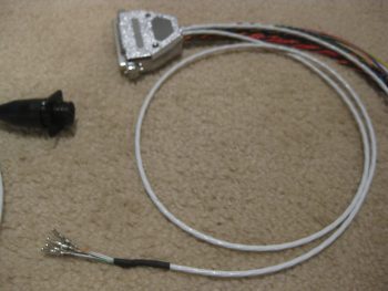
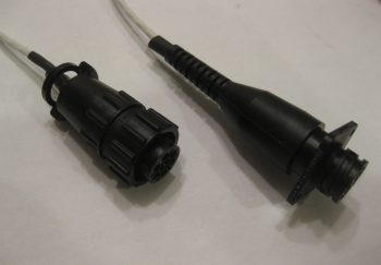
This concludes the connector upgrades for the autopilot’s pitch & roll servos, and the wiring harness pitch & roll servo cable feeds. The roll servo connector (below right) is pretty much complete, but I haven’t finalized it 100% since I will have to remove the connector to route the cable down the fuselage side & through the firewall. As for the pitch servo cable (below left), I still need to terminate the 2 autotrim wires and install those into the connector when it gets installed “for good” in the plane.
The last task of the evening was to review the mounting spacing of the Trig TT22 Transponder on the topside of the Triparagon cross shelf since it could potentially affect the mounting of both the front 1″ overhang on right-side cross shelf, as well as the PQD junction mount on the aft right side of the cross shelf (both on the underside of the cross shelf).
It’s dark & cold out right now so I’ll wait until tomorrow to cut the PQD Aluminum angle mounting bracket, as well as narrow down each of the forward 1″ x 1″ angled Aluminum cross shelf overhang tabs (for the CrackerJack parts) by about 0.4″, resulting in 0.6″ wide top arms. I’ll also assess all the wiring going through the PQD connectors to ensure the wires are physically inserted in a logical manner to keep the wire bundles as free-flowing and stress free as possible.