
Today was a good bit of spring cleaning. I took a couple bags of shop trash along with a few house trash bags to the dump on the way to the airport to deliver the canard to the hangar.
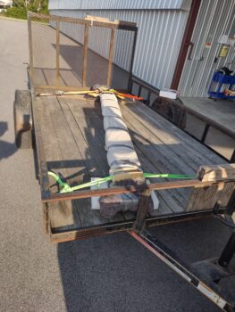
Of course I’ll need to store the canard before it gets mounted onto the airplane, so I brought along the converted/reinforced wing/painting sawhorses.
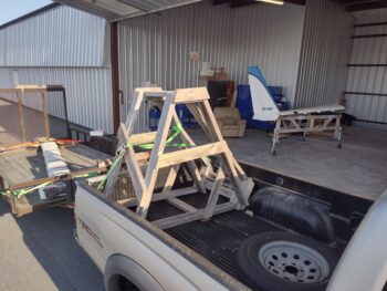
Here we have the canard in the hangar, still wrapped for transport after I picked it from Phil’s shop (where he buffed out the paint).
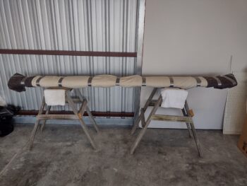
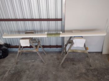
I then removed the protective transport wraps… Voila! Canard is officially at the hangar. I’ll note that once I ensure the elevators are balanced, I’ll bring them to the hangar and install them on the canard.
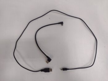
After returning home, I saw that my SkyRadar ADS-B IN receiver much shorter, right angle USB cable had been delivered. This 9″ cable will replace the current 3 ft. cable to make for a much tidier install between the SkyRadar receiver and the HXr EFIS’s USB hub.
I’m not sure if I’ve reported this yet, but when I checked continuity on the left fuel site gage video camera’s 3-wire connector, the power wire was not showing good. Those 3 wires are part of a 5 wire cable where the final 2 wires power the fuel site gage’s and strake baggage compartments LED lights.
First, the 3 wire video camera connector cable is spliced into the 5 wire cable near the original fuselage sidewall inside the strake baggage compartment… hard to get to. Second, I apparently got my wire color scheme (as per diagram) mixed up and had to play around with the wires for a bit to figure them out (a month back).
I’ve been pondering on how to repair the wire when I finally got around to testing the right side fuel site gage video camera lead. This time with actual video camera on hand (from the house) to check the wire coloring scheme. So my initial thought on the left side was that the yellow video feed wire was dead, but I was wrong. It was power… And wouldn’t you know that the same thing played out on the right side: the power wire failed the continuity test. Now, I know there is a small PCB in the camera connector leads, so I’m thinking some component is quite likely not allowing end-to-end continuity until power is applied. I say that as it seems very unlikely (but possible) that I jacked up only the power wire splicing on BOTH left and right video cameras.
Thus, I’ll operationally test the cameras first before engaging in any corrective action.
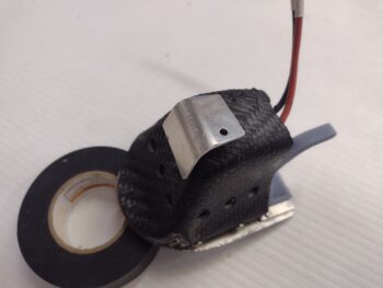
I then got to work on the Taxi Light. I’m mounting a small tab on it to attach a closing spring to ensure the taxi light is under pressure to close at all times. To do this I created an initial reinforcement/tab-mounting plate (pic 1) and then the tab itself (pic 2)… both from scrap pieces of aluminum (and yes, I’ll protect the mating surfaces from the carbon fiber).
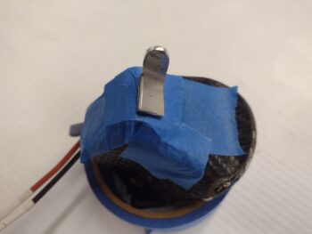
I then popped the taxi light into the nose and moved it inward to close… wow, way less room than I thought! A definite no-go on this tab position on the aft face of the light.
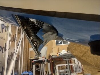
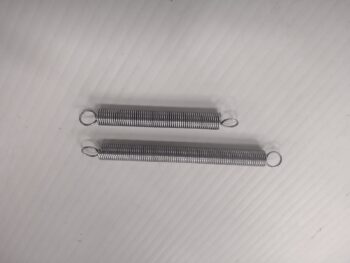
I’ll note exactly due to the positioning scenario above, I bought 2 different spring sizes to account for different positioning requirements.
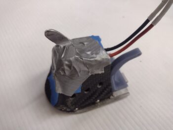
I then moved the spring attachment tab to the top of the taxi light cover, still angled aft.
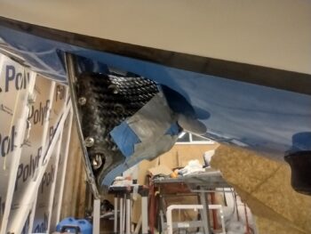
Hmmm, with the closing angle of the taxi light into its opening, barely any noticeable difference than above! Still a NO-GO.
Tomorrow I plan on significantly shortening the height of the spring attachment tab and then test out its positioning on the taxi light cover again.
It was getting late and I only had about 10 minutes before I needed to close up shop to rendezvous with my wife, Jess, for a late dinner (she worked tonight). So to get one more task off the list I quickly taped up the 3 static ports on each side of the nose.
You see, the original holes were 1/16″ diameter as per the plans BEFORE paint, but clearly not afterwards. The goal was to get the holes back to 1/16″ diameter without chipping any paint from around the holes (read: clean!).
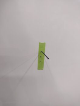
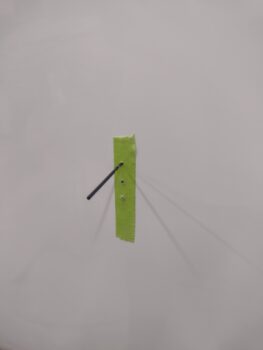
I started with a 0.048″ bit and drilled the holes, by hand, progressing up to 1/16″ (0.063″) through 0.052″, 0.055″, 0.059″ sized bits to again ensure no paint chips!
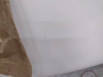
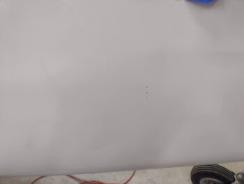
Requirement met and task completed: here we have the right side static holes (pic 1) and the left side (pic 2) all at 1/16″ (0.063″) diameter and vacuumed out clean.
And with that, I called it a night. More to follow tomorrow.