Today I started out by attaching about a half-dozen preprinted labels to component wires on the instrument panel. By the end of the evening I had printed out another 2 batches of heat shrink wire labels and attached nearly all of them to their respective wires. I have to say that printing out and attaching wire labels is definitely an exercise in perseverance and patience, but in the end I know it is way worth the effort.
Again, since the weather is so amazingly cold, I figured now would be a good time to get some really boring administrivia knocked out. It’s been forever since I inventoried my spreadsheet of 2-character component electrical codes, and since I needed another 3-4 codes for some newly acquired components, I spent well over an hour checking the list, getting rid of old, unused codes, and making up new ones for the new electro-whizzies that I’ve gotten in over the past month or so. I also printed out the codes and attached them to every electrical component without one, so all is up to date for all the electrical codes on my stuff!
Another can I had been kicking down the road was ID’ing and labeling my Inline Fuses. It really is the nature of the beast during a build like this for so many components to change as electrical system design and configurations change. I’ve had “IF00x” listed out for almost all my inline fuses for probably over a year now. And since my system is much more dialed in and closer to final than a year ago, I figured now was the time to figure out the sequential numbering for all the Inline Fuses. So I got that list knocked out and updated, then just as I did with the 2-character component codes, I printed out labels for the Inline Fuses and attached them to the appropriate inline fuse.
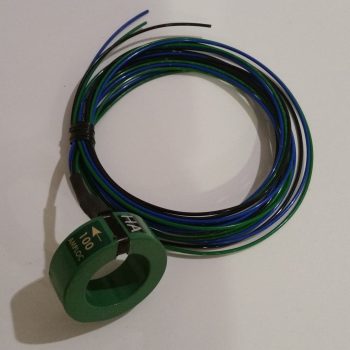
When I checked the mail today I finally received the CS-01 Hall Effect sensor that I ordered from GRT. As I was configuring the settings on the EIS4000, I did a quick read on how to set up the CS-01. With it in hand however, today I did some much more thorough research on just how to install the CS-01, including going back and looking at my notes. I had a few questions, and between the GRT forum and the AEC forum I was able to find the answer…. plus a few other nice-to-know tidbits [Note the “HA” code label].
Along with tweaking the settings for the CS-01 Hall Effect Sensor, I had some other updates I needed to do on the GRT EIS4000. So I hooked it back up, fired it up, and tweaked some limit configurations and auxiliary port settings.
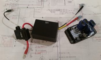
I then worked on constructing some new power and ground cables for the “Deslumpifier” AKA Voltage Slump Eliminator. Since the power IN for the Deslumpifier needs to be fused, I just picked a location on the Triparagon that allowed me to simply use a robust inline fuse holder with leads as the main power cable. Right now I’m fusing it with a 7.5A ATC fuse which I think is a good starting point. To match the massive leads of the inline fuse power cable, I used a black 14AWG lead for the ground cable.
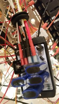
I then cut, labeled and re-terminated the existing power and ground leads to the GNS480 to allow them to be hooked up to the Deslumpifier. After I finished the GNS480 leads, and before final hookup, I tested the Deslumpifier’s output (to ensure no power surges into the GNS480) and it showed 13.84 volts… definitely good to go. I then terminated all power and ground leads into the Deslumpifier (note the grommet).
Backtracking just a bit . . . actually before I went final with hooking up the leads above, I cut an initial hole, then widened it into a slot on the end of the Deslumpifier cover where the leads connect onto the board. After stuffing all the leads into the grommet I had a good idea just how wide the grommet hole/slot needed to be, so I then finalized cutting the appropriate sized slot for wire lead access into the Deslumpifier, including the grommet of course. I then slid the grommet into the cover’s end slot and mounted the cover onto the Deslumpifier.
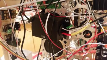
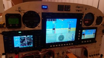
With the wiring looking good on the Deslumpifier, I then powered up the panel, including the GNS480. Below is a wide angle view of the panel showing that the Deslumpifier works fine in powering the GNS480 in battery mode. Much later on I’ll conduct Phase II testing which will be during actual engine start to see if the Deslumpifier will keep the GNS480 from rebooting.
I have to say that although there was a lot of mundane work that took place today, it was quite productive. Tomorrow I’ll continue working on my instrument panel electrical system to-do list.

