
Snooze alert! The stuff you’re about to see is boring …. good heavens, even I’m bored with this stuff! I tell ya, the one good thing about working seemingly endless hours on the mundane tasks is that it really makes you itch to get back into the shop and sniff epoxy.
I spent over 5 hours yesterday scrubbing & updating every wiring system diagram I have on hand. I figure that if all goes according to plan that this will be the last winter I have before my first flight to knock out all this nitnoy stuff…. again, much of it that I haven’t gone over in quite a while.
Today I spent a few hours on the phone discussing build topics with another Long-EZ builder, it was a great discussion but it put a sizable dent in my schedule. Why build airplanes when you can TALK about building airplanes?! … ha!
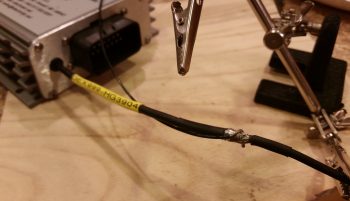
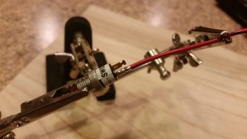
I then did some more cleanup on a few more electrical-related docs before getting down to business. After attaching about a dozen wiring labels, I then stripped off some of the heat shrink over the solder splice on the Electroair electronic ignition’s control unit ground wire.
I had removed a Deutsch connector a while back and simply soldered the 2 wires together, but now I needed access to that solder joint to splice yet another wire into the mix: the 22AWG lead that will be the negative input (V- In) to the AD626 op amp board for Spark Advance reporting to the EIS. Again, the signal coming out of the Electroair control unit is too weak so I need to literally amp it up by a gain of 10 so that the GRT EIS can use the strengthened signal to report the Spark Advance to the EFIS screen.
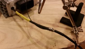
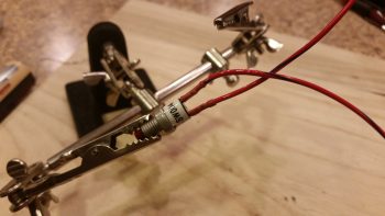
After exposing the original solder splice joint, I then soldered the 22AWG wire into the joint.
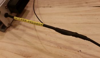
I then recovered the new solder splice with some more heat shrink.
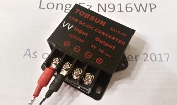
Next, I focused on my 12V-to-5V power converter. What will it be used for you ask? Well, in order to use an aft-looking wide angle video camera that I’m going to mount at the top of the headrest, I need to use a 5V power signal to drive it. In addition, I want to mount and use my Bendix/King AV8OR portable back-up GPS in the lower left corner of the panel, which too uses 5V power.
So I made up, labeled and terminated the power and ground wires for the 12V-to-5V power converter and screwed them in place on the terminals.
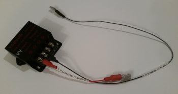
I have a power wire jack on order for the BK AV8OR GPS, and I need to acquire some 24AWG wire before proceeding with wiring up the video camera, so below is as far as I’m going to go on the 12V-to-5V power converter for now.
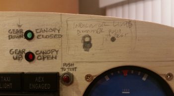
I then assessed and marked the plywood instrument panel mockup to drill a 3/8″ hole for the panel ON/OFF indicator LED lights’ dimmer.
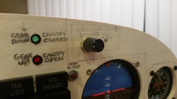
After drilling the hole and cleaning up the sawdust, I then test mounted the dimmer switch and knob…. not bad.
I then got to work on cutting and soldering the panel ON/OFF indicator LED light ground wires to the dimmer switch.
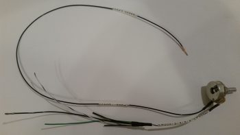
While I was in the vicinity, I also removed the panel ON/OFF indicator LED lights’ Push-to-Test switch and soldered the power leads to it as well.
I then added heat shrink over the soldered leads for protection.
Tomorrow my focus will be on getting the Power Busses labeled, which was part of my tasks today in doing some final determinations on what components go to what tabs on the power busses. I also updated some ground bus tab and connector pin assignments.
Yes, this stuff can be mundane and boring at times, but it is quite necessary and has proven worthwhile considering the number of small oversights that I keep finding on my diagrams and spreadsheets. I think nearly all the clerical mistakes have been corrected now, allowing me to start off 2018 with all my electrical system docs and diagrams in order!
Great work! I wonder if you’d consider making a video of some of your wiring techniques? Soldering methods etc. I know there are a lot on YouTube but there are specific ways of doing 100% right, the strain relief, the shrink wraps and so on. That would be of huge interest to some of us. I always wonder on the labeling too…can you get the heat shrink on after you solder and crimp? How hard is it to relabel something later? Any tricks to that. I can imagine a loom with a couple of label changes needed. Does removing and installing pins for this make problems? The devil is in the details to make reliable systems – thats the info which is hard to find.