
Well, as not that uncommon in this build, what was supposed to take a few hours ended up taking up every minute of my day today and propelled itself into the wee hours of the morning.
But my immediate task is done . . . for now of course! I tried a few different ways to get this on the screen, but alas my JPG captures on my CAD program suck. So I just took a screen shot (pic below). It gives you a general idea of what I was up to all day yesterday sorting through essentially a massive pile of spilled spaghetti.
I pretty much assessed every wire and every connection coming out of the GRT HXr EFIS (PFD), GRT Mini-X EFIS (MFD), Garmin GNS480 GPS receiver, and Trio Pro Pilot Autopilot. I identified if the wires would simply be run from point A to point B, or in a twisted pair or shielded conduit, all based on the requirements coming out of the installation manuals or the manufacturer’s guidance. Where there was no specific guidance I turned to words of wisdom from the grand pupa of aircraft electrons, Bob Nuckolls, by referencing his masterpiece, The AeroElectric Connection.
In addition I clarified some info via phone calls and emails as I did with Chuck from Trio Avionics. And will do the same with GRT tomorrow.
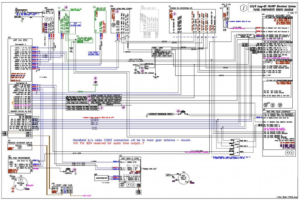
As I mentioned yesterday, I also labeled every RS232 serial pair and ARINC 429 pair for the data signal wires with their respective configuration labels and correlating baud rates that will be used when setting up the individual components to talk nicely amongst themselves. I was also able to reallocate and free up some serial ports based on my newfound knowledge and tweaking of my system (also facilitated by some updated manuals such as a new 2017 install manual for the Mini-X). This, in turn, both reduced the physical number of wires and allowed me to clear off unneeded ports that I was tracking on the diagram above.
With the wire types identified for each port, I was then able to massively rework my Panel Quick Disconnect (PQD) connectors and consolidate all the HXr EFIS harness wires on the J4 PQD 37-pin D-Sub connector. I was just short a couple of positions, so I moved the power off the J4 connector and repurposed the J10 connector label for a new 4-pin mini-Molex power connector (HXr primary, secondary and tertiary power plus ground). The old J10 connector got bumped down the line and is now J12.
Below is a page out of my connector pinout tracking sheets packet. I track literally every wire, pin & socket in every connector on this aircraft. As you can imagine, I’m waiting for the day when I can stop updating these sheets!

In addition, I did exactly the same thing in consolidating every wire for the Mini-X through the J3 PQD 15-pin D-Sub connector. This is very significant in that it allows me to simply unplug & remove my HXr EFIS by disconnecting only 2 connectors: a D-Sub & mini-Molex (ok, and a USB cable . . . you got me!). Moreover, If I choose to, I’ll be able to disconnect & remove my Mini-X EFIS by disconnecting 5 things: a D-Sub, a USB cable, the GPS antenna cable, and of course the Pitot & Static connections.
After I finished reworking my panel component wiring diagram and the pinouts for the 3 PQD connectors, I then did a scrub of every wiring diagram I have on hand, which is nearly 30 diagrams. In addition to the panel component wiring diagram, I had to do significant updates to 8 other diagrams.
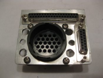
To help bring all this massive paperwork drill to life so you can see it in the physical world, I went back and snagged a couple shots of the Panel Quick Disconnect (PQD) connectors in the PQD bracket (still in its rough state before cleanup) so you can see what I’m talking about. The 37-pin D-Sub J4 HXr connector runs across the top, while the 15-pin D-Sub J3 Mini-X connector runs down the right side. The big round 24-pin connector, which admittedly is sparsely populated now (read: scalability) is the P6 AMP CPC connector.
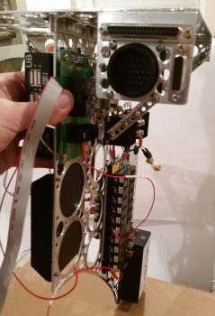
 Here’s a shot of the PQD connector bracket at the aft right corner of the Triparagon’s top cross shelf. The PQD bracket is situated right below the aft face of the Trig 22 Transponder. In addition, the PQD connectors are only a scant 4.5″ (IRRC) from the aft side of the HXr and Mini-X . . . so close in fact that I could not physically install the cable clamp on the aft panel-side P6 AMP CPC connector and still have clearance to run all the wires!
With my short deviation back into the world of electrons over (…for now!), I can get back to tackling the GIB area and start seriously planning on knocking out the nose and canopy (with perhaps a quick sideline tryst to finish the wheel pants?!)