
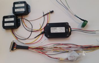
Today I got all the wires labeled on the GRT EIS4000 Engine Info System wiring harness. In addition, I was able to label the wires near the actual GRT Manifold Pressure sensor and the GRT Hall Effect sensor. Since I ran out of wire labels —having burned through 2 cartridges in less than 3 days— the labels on the distant end of these wires (where they connect either to the EIS4000 or to ground) will come later. Lastly, I was able to label 2 out of the 3 wires coming out of the left and right fuel tank level sensor control heads.
As you can see, I clearly made a sizable dent in the aft fuselage-located components’ wiring labels.
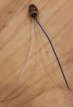
In my effort to lean as far forward as I can in getting the electrical components prepped as much as possible to facilitate as quick of an electrical system installation as I can eek out, I went ahead and soldered the 2 wire leads to the GIB PTT button. These will get soldered onto the tabs of the GIB headset phone jacks when that gets installed.
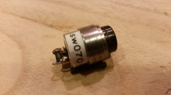
Since I didn’t have standard sized solder tabs on the back side of this button to solder onto –remember, this came out of my F-15 throttle handle– I soldered the leads onto the legs of the existing capacitor that was mounted in place. Nonetheless, when I toned it out with a continuity test all was good.
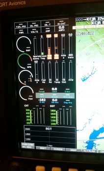
I then spent a couple of hours researching and doing some initial messing about with configuring my engine data info display on my HXr EFIS screen. After seeing and assessing how I can go about configuring it, I got into the manual to find that I missed a HUGE piece of the installation puzzle . . . again, assumptions will bite you in the butt!
Since the EIS4000 is a standalone panel mounted instrument in its own right, but that can also be summarily hidden away so it’s sexier cousin (HXr) can get all the praise in presenting such wonderful data in bright shiny ways, all the parameters on the EIS4000 must be zeroed out with all the engine data max/min limits set in the EFIS. Why? Well, if an alarm rings off on the EIS4000 (remember, it’s a standalone instrument that shares its data with the HXr EFIS) with it tucked behind the GIB’s head, then there is no way to turn the alarm off!
Thus, by zeroing out the engine data parameters in the EIS4000, it then becomes an information collection point and conduit to further pass the data (and parameter limit control) to the HXr. So along with deciding what exact info I want displayed, and how, a new task on my list is to now transfer all the engine data parameter limits from the EIS400 to the HXr (and Mini-X) and then zero out the engine data parameter limits on the EIS4000 box (except for the Aux functions… those are simply replicated between the two units).
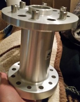
Finally, my Winchester, Virginia-based engine builder, Tom Schweitz, called to ask me some configuration questions on the engine for the build next week. To make absolutely sure I was answering his question on prop flange bolt size, I pulled the prop flange to confirm. I figured since this a close-in objective, I would snap a pic of it so we can all get into an engine frame of mind….
Since my truck needs some TLC, especially before I make a couple of trips up to Winchester, VA and back…. the last trip most likely with engine in tow, I need to take a couple of days off my airplane building effort to focus on installing some new valve cover gaskets on the truck motor. Thus, the next 3-4 days will be very light, if any, on the airplane build.